


![1918 Spring Offensive Wargame | Full Rules Overview with John & Gerry (WW1 Tabletop Game) [7 Days Early Access]](https://images.beastsofwar.com/2026/03/unboxing-warfulcrum-games-1918-spring-offensive-review-coverimage1-225-127.jpeg)


Motorised Painting Handle


Recommendations: 347
About the Project
Ok, maybe it's not cool to admit it, but I'm the kind of soft sap who cries at DIY SOS - seeing people's lives changed beyond measure by the goodwill of a community of skilled people is incredible. So when I read Ryan's post about accessibility (https://www.beastsofwar.com/featured/roll-for-insight-wargaming-accessibility/) in the hobby, I figured "here's something I can get involved with". I was particularly inspired by the big button game controllers, and recall how one of the things John kept "banging on" about in his recent review of a painting handle is how comfort - in either hand - is important. Which got me thinking about people who maybe couldn't hold their miniatures comfortably, but still needed to be able to hold, position and rotate them for painting. Luckily, motors and electronics and making circuit boards is "my thing". So I set about making a motorised painting handle. Hopefully someone might find it useful. I plan to post the schematics, code, laser-cutting files and everything else needed should anyone else wish to make one too....
Related Genre: Game Aid
This Project is Completed
Where it began....
Ok, maybe it’s not cool to admit it, but I’m the kind of soft sap who cries at DIY SOS – seeing people’s lives changed beyond measure by the goodwill of a community of skilled people is incredible.
So when I read Ryan’s post about accessibility (https://www.beastsofwar.com/featured/roll-for-insight-wargaming-accessibility/) in the hobby, I figured “here’s something I can get involved with”. I was particularly inspired by the big button game controllers, and recall how one of the things John kept “banging on” about in his recent review of a painting handle is how comfort – in either hand – is important.
Which got me thinking about people who maybe couldn’t hold their miniatures comfortably, but still needed to be able to hold, position and rotate them for painting. Luckily, motors and electronics and making circuit boards is “my thing”. So I set about making a motorised painting handle. Hopefully someone might find it useful.
I plan to post the schematics, code, laser-cutting files and everything else needed should anyone else wish to make one too….
Now there are plenty of robotic arms readily available across the intertubes that, on the face of it, would be ideal to hold and manipulate miniatures for painting. You can buy entire robotic arms relatively cheaply (simply Google “servo arm” to see how many and how cheap they are).
In fact, my first thought was to create a servo arm but, having experience in this area, I remember how difficult it is to create “damping” at the extremes of movement; the arm doesn’t move softly from point to point – there’s no “ramping” up or down of the speed – it simply heads to each new position as quickly as possible.
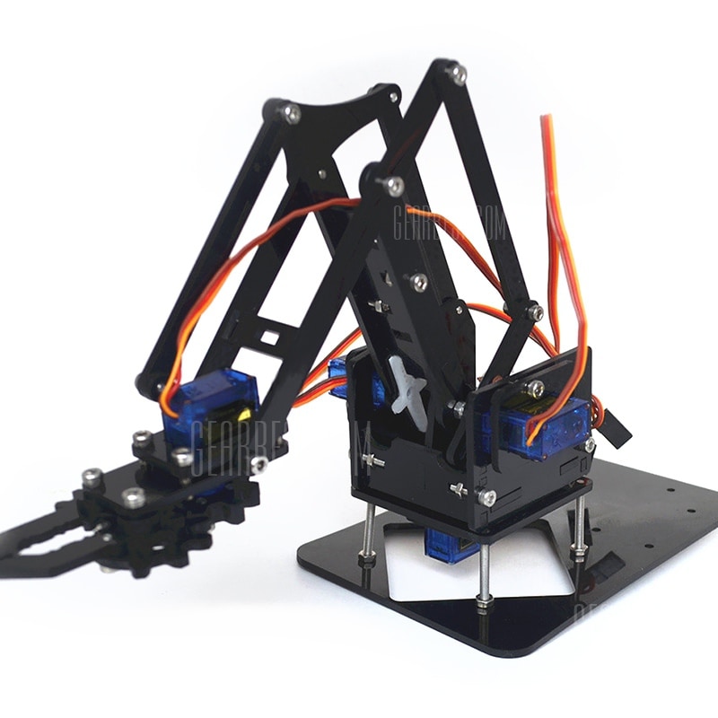 example of one of the many servo arms available online
It’d be no good placing a heavy lead/pewter miniature in the jaws, moving it into position and have the robot arm fling the mini across the room! What we need is something a little more controllable…..
....I can't begin to knowing...
The 28BYJ-48 miniature stepper motor is brilliant for all kinds of homebrew robotics projects. Firstly, they’re cheap. Like a quid-a-shot cheap (if you source directly from China via AliExpress or Taobao). I had loads of these hanging around. Secondly, they’re (relatively) easy to interface with.
I find sticking a ULN2003 (or a ULN2803A) array onto the pins the easiest way to get these motors spining, controlling them via a microcontroller (either Microchip’s PIC or AVR’s Arduino).
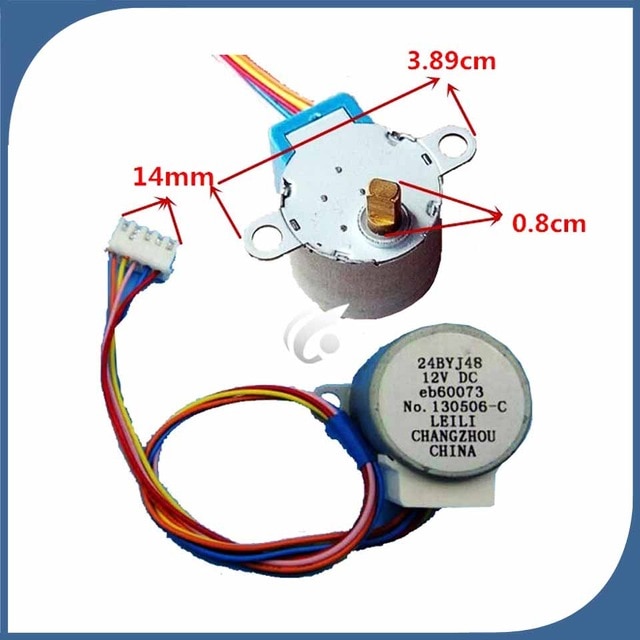
The other nice thing about these little stepper motors is that they are quite powerful. As in, for a small form-factor, and for a low voltage, they’re quite torque-y (yep, that’s a word, don’t bother checking). Inside the casing is not just a tiny motor, but also loads and loads of gears.
In fact, these motors are geared down to about 1:4000 or something crazy like that. In short, it means that they’re also quite slow. For home robotics, this might be a problem. For us, it’s exactly what we want!
 stepper motor internal wiring
Stepper motors aren’t quite as straight-forward as regular motors; you don’t just put power to them and watch them spin. They have a number of coils which need to be activated in a particular sequence. The order in which you activate the coils determines the direction that the motor turns.
The benefit over “regular” dc motors is that you can stop the stepper motor dead, after a specfic number of steps have been counted – this makes them perfect for exact/precision positioning. In fact, we’re using the motor more like a regular motor (it’ll either be on or off, in either a clockwise or anti-clockwise direction) but taking advantage of the gearing to give us strength we wouldn’t otherwise have (and did I mention, they’re cheap too!)
To make this motor turn clockwise, we need to provide it with 5v, and ground certain pins in sequence:
If, for example, we pull the orange and yellow connections to ground, this creates an electromagnetic field in both coils, pulling the centre of the motor into the “bottom-left” position (SW point in the diagram above).
Now, this is where we control the direction.
If we then pull the yellow and pink pins to ground, the centre of the motor is drawn towards the top-left/NW point in the diagram. From here, pulling pink and blue to ground creates a magnetic field which attracts the centre of the motor to the top-right/NE point, and finally, pulling blue and orange to ground attracts the centre of the motor to the bottom-right/SE point.
Start again from the first state, pulling orange and yellow to ground and the motor has completed one full revolution.
Obviously, to get the motor to turn in the opposite direction, you activate the pins in the opposite sequence (orange and yellow, blue and orange, pink and blue, pink and yellow).
(Note for all your techy-nerds: yes, we could also activate each coil individually, creating a micro/half-stepping sequence, but by activating two coils at each time, we keep torque to a maximum).
But I know it's growing strong...
Ok, song lyrics as titles aren’t going to get me through the rest of this project, so I’ll leave that alone right now.
Now we’ve got our motors spinning, it’s time to get super-nerdy. (Skip this post if you’re not much bothered about how it’s made, and I promise, on the next one, I’ll do a bit more on the what/why).
I decided to use two back-to-back motors for the up/down movement, and a single motor on the top, to create the left/right rotation. As we’ve seen, driving stepper motors requires a bit more work than simply switching power to them, so I thought I’d shove an Arduino on to control them (normally I’d use PICs but Arduino seems to be really popular and, if this is going to go open-source so anyone can create their own, it makes sense to use what most people are comfortable with).
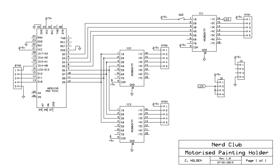
Here we’re using one set of signal wires to control two ULN2003 transistor arrays but if you look closely, you’ll see that one set are numbered 1,2,3,4 and the other 4,3,2,1 – this acheives the same result as driving one stepper motor in the opposite direction to the other.
The schematic helps with the placement of wires and traces when making a custom PCB.
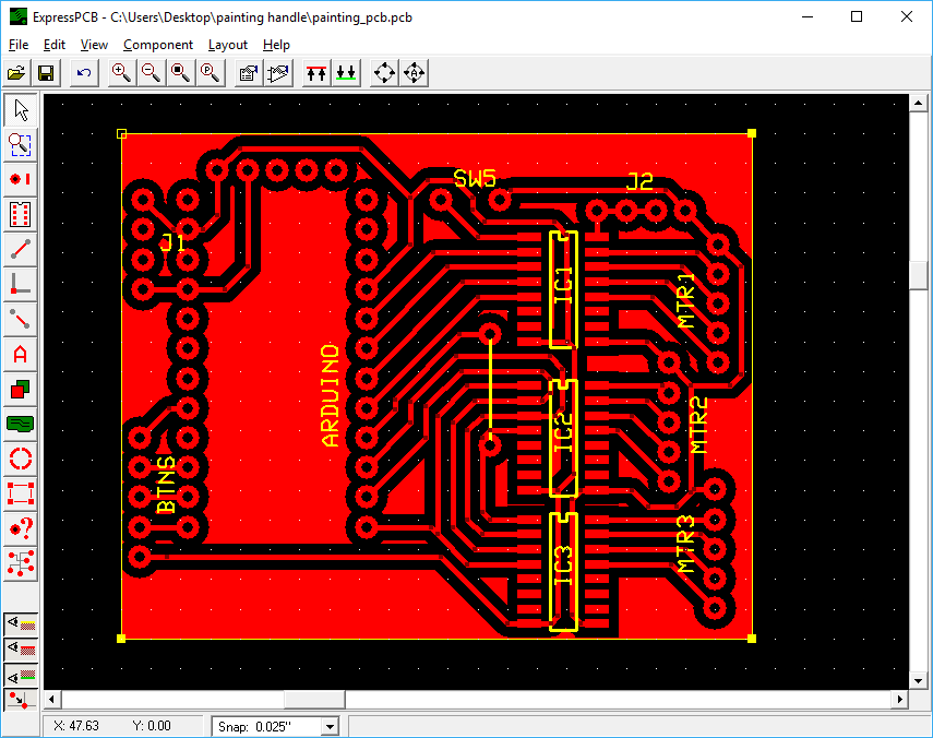 PCB layout is much easier if you can link your layout software to a schematic
Creating laser cut files
I tried 3d modelling software. I’ve love to be able to create 3d models, get all the measurements just right, and then simply send to a printer/laser cutter. But I just can’t seem to get my head around it.
I’ve spent a small fortune of Udemy courses, trying to learn Blender, 3DS Max, Fusion 360 etc. but I just can’t seem to “think in 3D”. Since the shapes are cut from flat sheets, I tend to think in 2D, draw the necessary shapes, cut them out, throw half away, amend the drawings and repeat, until something workable appears!

Drawing are then tidied up, removing all the guidelines and other nonsense shapes I’ve used to get distances and tolerances about right, and sent to the laser cutter.

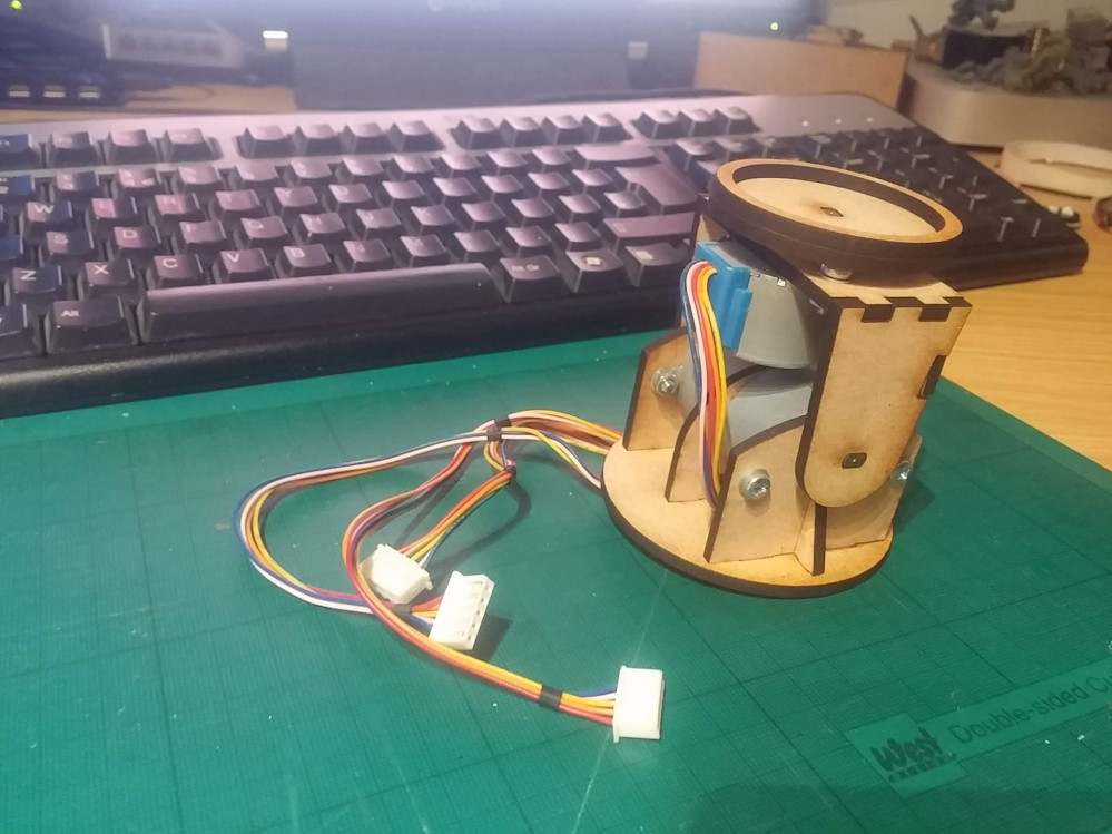
Then the whole thing bolted together and checked for clearance, and to make sure all the moving parts move as required. At this point, all that’s required is some “firmware” on the Arduino controller and we can try this thing out….
Motorised painting handle - first test
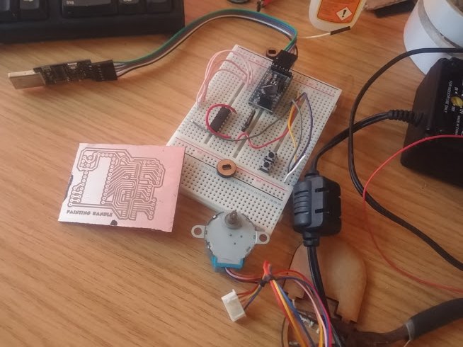 more homebrew pcb goodness!
One of the great things of having access to a laser cutter and few litres of ferric chloride is that it’s pretty easy to design, etch and manufacture your own PCBs in about an hour or so.
Here’s the current design, hooked up to the motors via a plug-in breadboard prototyping system. In the final design, things will be much neater and all the nasty wires hidden away, but for developing and debugging, being able to easily unplug pins to work out what’s going on is invaluable!
So far, it’s just a two-axis movement. But it should be more than enough for 90% of miniature painting. I might stick a third axis on it (to allow the entire base to rotate) but that would mean introducing tricky stuff like shift-registers as there aren’t enough pins on a regular Arduino Mini to control four stepper motors AND up to six input buttons.
One quick amendment I made after testing was to add a speed controller. Even at 4,000 steps per revolution, with a delay of just 2ms per step, the motors were making one complete revolution every few seconds. This might sound slow, but given the size of the frame the motors sit in, this actually translates as a lot of movement over a very short space of time.
A simple voltage divider on one of the analogue input pins means I can now change the delay between steps from anywhere between 2ms and 50ms – thus speeding up or slowing down the motors significantly.
Now to build a button interface and see how it all works out!
Adding a joystick
I started thinking about adding a third motor, and how this would require a whole load of other pins to be used and possibly even a complete overhaul of the current electrical circuit.
With up to six buttons (let’s call the axis pitch, yaw and roll, but I’m almost certain that those are not correct) and a speed controller, plus four pins for each of three motors – that’s a lot of input/output line for what was supposed to be a quick-and-simple over-the-weekend kind of project.
A quick rummage through my bits box (while many people have Space Marine arms and legs and heads and blaster guns in their bits boxes, mine has stuff like resistors and sensors and pushbuttons) and I found what I was looking for…
 cheap and easy to interface with, the internet is awash with miniature joysticks
Nothing screams “disability friendly” like big chunky buttons.
And for users with poor fine-motor skills, they’re an absolute godsend. But this project is less about providing for users with fine-motor issues and more about creating a painting handle that is more comfortable, and easier to use, than simply gripping a miniature for extended periods of time.
So I figured that a relatively small joystick – that still requires a degree of motor skill to operate – would be suitable for manipulating the electric motors; it also frees up a few input pins (always useful) and, most importantly, provides both direction and speed control in two different axes.
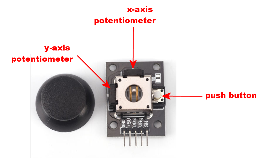
The joystick works by placing two potentiometers (variable resistors) at right-angles to each other. This means that, instead of simply and up/down command (as we get with pushbuttons) the joystick generates a range of values, depending on how far it’s been pushed.
The pushbutton is only really activated when the joystick is in the centre (so you can’t, for example, push down the button and move the joystick at the same time – moving the joystick causes the button to release).
However, having a pushbutton means that we can simply cycle through each of the motors to put it under control of the joystick; this gives us the option of being able to control one, two, three or any number of motors, using the same joystick.
Time to change that PCB layout (again).
This time it’s going to be awesome!
Testing an analogue joystick and stepper motors
In theory, having an analogue joystick should mean about 500 degrees of control in each direction (since the joystick returns values 0-1023 for the x-axis and 0-1023 on the y-axis, if the centre point is 511,511 we should expect a nice range of values from one extreme to another).
In practice, getting a nice wide range on the joystick is really difficult. It has a large “dead spot” at the end of each travel, meaning the tiniest amount of movement makes the input values change by about a hundred. Just a few millimeters of movement and the joystick has “maxed out”.
With this in mind, I changed the code to change the speed of the motors over just a few discrete positions.
- Barely touch it and the motor barely moves
- Push it a little bit, and the motor turns at about 1/3 speed
- Just before maxing out the travel on the joystick, the motor is running at about 2/3 speed
- At the full limit of movement, the motor runs at full speed.
When connected up to a couple of motors, we can see how not only can the maximum speed of the motors be limited, but just by using the joystick (instead of constantly fiddling with the speed controller) we can get them to spin at faster/slower speeds
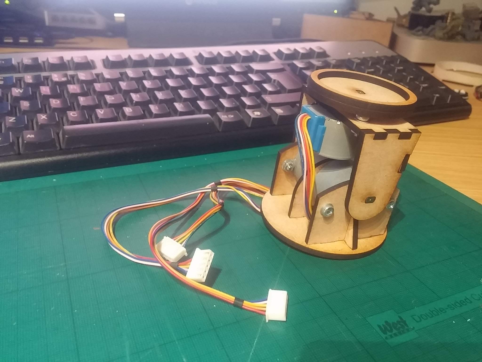
Finally getting somewhere....
While it’s fun to connect motors to microcontrollers and mess about making them spin, it’s really only when they’re actually connected to something that it makes much sense.
So far, the PCB supports a “simple” painting stand – you can rotate the top and you can angle the vertical support. In fact, during testing, it seems like this gives a really good range of angles to attack your miniature from, while painting.
I still quite fancy the idea of putting the entire thing onto a round base that can rotate, just to cover all “degrees of freedom”. Maybe that’ll come in a future development.
A friend once told me that “finished is better than perfect”. I’ve never quite understood; until it’s perfect, how do you know if it’s finished? That’s probably why I’ve a workshop full of unfinished projects, each filled with “potential to be awesome”!
But, for a “quick” weekend project, I think this is as done as it needs to be. Obviously, I’ll put together a nice enclosure, get all those nasty tangle-y (yep, that’s also a word) wires tucked away and stick a micro USB socket on the pcb (so you can run it from a phone charger, instead of requiring its own dedicated power supply).
Look out for the code and PDFs of the circuitry, PCB layout and laser-cutting files in the coming days, so you too can make your own!


![StarCraft Tabletop Miniatures Game Pre-Orders Live Now [Updated]](https://images.beastsofwar.com/2026/03/starcraft-tmg-news-cover-600-338.jpg)


![Mounted US Cavalry On Kickstarter For Dead Man’s Hand! [Updated]](https://images.beastsofwar.com/2026/03/us-cavalry-main-600-338.jpg)