


Cyberpunk Advertising Signs


Recommendations: 142
About the Project
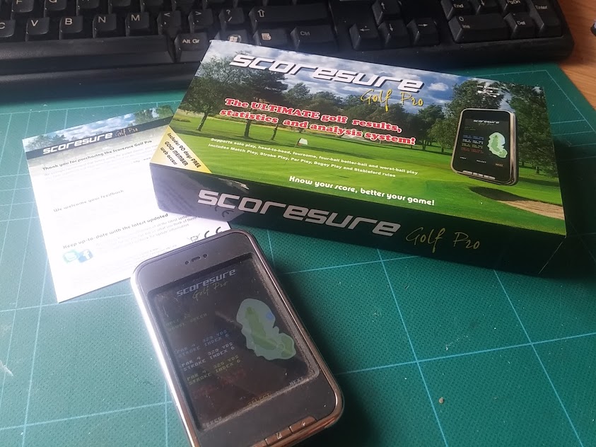
Nearly ten years ago, I hacked open a K838 digital photo frame and used the screen to create my own battery-powered pocket device. I turned it into a golf-score keeping gadget for my son-in-law (I don't play golf) and was convinced to turn it into a commercial product. The month before product launch, the worldwide ban on using mobile phones on golf courses (competitively, but it also held true for many amateur clubs too) was lifted. A year's hardware development was reduced to an app overnight! I found one recently and tried to repurpose it for something far cooler.
Related Genre: Cyberpunk
Related Contest: Spring Clean Hobby Challenge (Old)
This Project is Completed
What's this all about then?
Many years ago (checks the calendar and realises it’s over ten years ago!) I hacked a few K838 digital photo frame keychains and got them to work with my microcontroller of choice (at the time) a PIC 18F4550.
I was encouraged to try a new business venture – a digital golf score-keeping device, that let players access live course information, record their scores and download them onto their computers for analysis through a website. The demand for such a device came because – at the time – use of mobile phones was strictly barred on golf courses (not just competitively, but many local courses had a no-phones policy).
I invented a device that could draw graphics and sprites onto the screens (which in turn came from a major mobile phone manufacturer so were relatively cheap to source) and store data in an external eeprom chip, along with a menu-based UI.
I booked a stand at the Golf Show in the London Excel Centre, had 500 units made and sent over from a factory in China and spent a week programming my custom-made devices with my own firmware, having spend three months on an all singing-all-dancing website.
Two weeks before the big launch and disaster struck – the ban on mobile phones was lifted and overnight rendered my new hardware useless. It had been replaced by an app (although nobody went on to create the app to replace my device, and I lost heart and didn’t bother myself).
This left me with hundreds of useless devices!
I re-programmed a few hundred and sold them on to a music shop in Italy, who turned them into digital instrument tuners. A few were sold to an industrial control panel manufacturer, to make a small-form user interface for their own hardware.
Many hundreds eventually ended up in landfill.
I never thought about them again. Until last week, when, rummaging through my loft looking for some old miniature paints, I came across a box with about thirty left over devices.
I was in the loft looking for crafting materials because I was building a cyberpunk city using mdf terrain for a tabletop skirmish game. I figured that if I could take just the screen and lose the enclosure, I could create some amazing Blade Runner-esque advertising hoardings.
The only trouble was, I had nothing else to work with. No code. No schematics. Nothing. Just a bunch of devices. And the knowledge that, once upon a time, I was clever enough to make them display my own images.
I was certain that if I was clever enough to do it once before, it shouldn’t be impossible to do it again – even if my brain is ten years older, carrying a decade more trivia and useless information, and ten years more tired!
Working out how it works
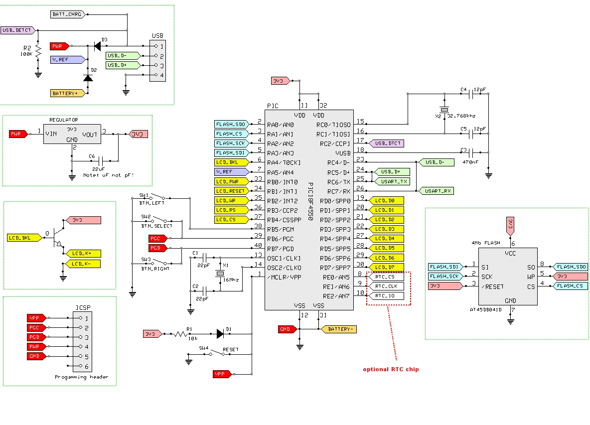
The first thing I needed to do was create some kind of schematic of which pins of which chips connected to which other pins on which other ICs. This involved the painful, tedious job of putting a multimeter onto every pin of the microcontroller, eeprom chip and every other IC on the circuit board, then finding which other component it was connected to. This was a long and slow job.

But eventually, I got an idea of which pins connected to what.
With this information, I was able to start again. From scratch. From the very start.
The original firmware had taken about four months to develop fully. I’d decided that this was going to be a quick-and-dirty project, and gave myself a full working week (Monday – Friday) at most. If it wasn’t working by the end of the week, I’d give up and simply paint large advertising hoardings on by buildings instead!
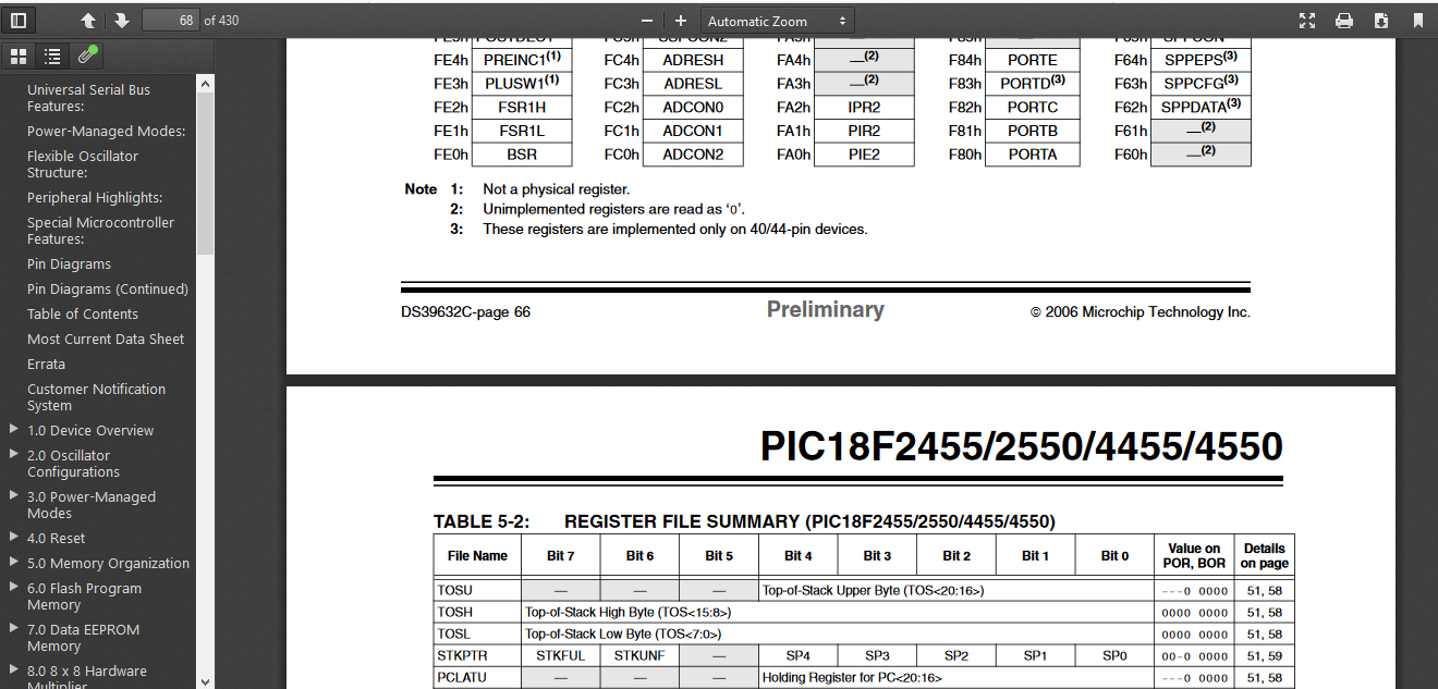
This meant reading and dechipering lots of datasheets….
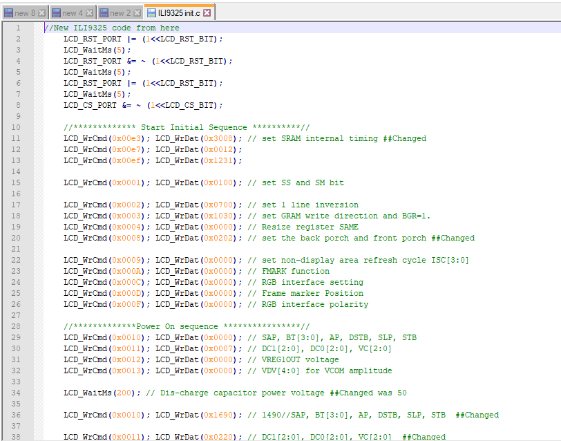
… and, not knowing (or rather, not being able to remember) anything about the controller on the LCD screen, trying out lots of different intialise routines to try to get the screen to switch on
It took me no less than two and a half days to get the screen to even switch on! And when it did, the display was nothing but a load of static. This wasn’t going to be as straight-forward as I first thought…..
Getting things working
Two days of head-scratching and turning the air blue and I finally had a breakthrough. Admittedly, it doesn’t look like much. It’s a screen full of static.
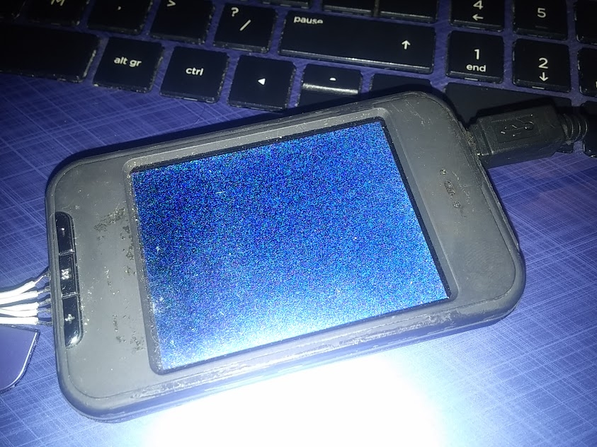
But the point is – you can see the static.
Finally, after trying about twenty different initialisation routines, I stumbled across the one that worked. And with the correct initialisation running, the correct voltages were generated through the charge-pump capacitors (I know, me neither if I’m honest) and the screen turned on.
Knowing the init routine gave me a bit of a steer as to the controller chip inside the actual LCD screen. And knowing this, I at least had some idea about which memory registers needing poking to get it to display data.
It was just a matter of finding out the layout of the screen and the order of sending data to it; does it require a co-ordinate point for every pixel, or can I set a start and end point, and then flood it with a load of colour? Does it draw right-to-left, left-to-right, top-to-bottom?
All of these required hours and hours of poking about, changing code, uploading, trying it out, recording which pixels had changed to which colours and so on.
Eventually I had some encouraging progress:
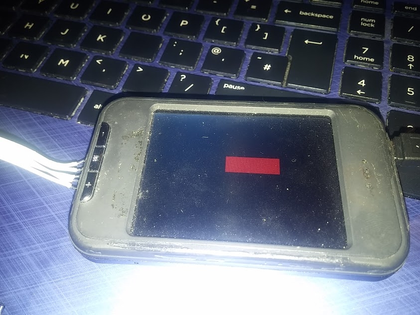
Yes, it just looks like a crappy red rectangle to you.
To me, this was a major breakthrough. Note that there’s no longer a screenful of static. To me, this was a big deal, not a crappy little rectangle.
It meant that I could decide which area of the screen to draw on, and which colour pixels to draw in that area. To re-create a bitmap image on the display is just a case of repeating this process – define an area and fill it with one colour, then define another and fill with another colour – and so on and so on, until the entire image appears.
Which meant I was now onto the second – and probably more difficult – part of the project: storing image data into the onboard eeprom chip. And then, more importantly, recalling it back out and turning the bitmap data into a series of coloured pixels on the screen.
Which means I need to find out a bit more about this eeprom chip.
Now, where did I put that multimeter….?
Storing image data
The screen is (relatively) cheap. The microcontroller a little 8-bit workhorse. It’s not particularly fast (running at around 4Mhz as the original device was battery operated) and the amount of space for storing images is limited at 4Mbits.
In human-speak, that’s about half a megabyte of storage. Not massive. Then again, the ZX Spectrum had only 48k of memory and they managed to cram 300 rooms into Head over Heels, so limitations shouldn’t… erm…. limit us to much.
The screen size is 240×320 which is a massive 76,800 pixels. If we tried to display full-colour 24-bit images, we’d have enough space for just two full screen pictures.
We’re going to need some kind of compression to store images! But not too much – it’s only got a puny 8-bit processor in there, so nothing too number-crunchy.
I decided on a compromise – a limited palette and RLE (run length encoding) to store the bitmap data. So instead of every pixel taking up three bytes (one byte for each of the red, green and blue channels) the first thing to do is create a palette, and refer to each colour by index number (a kind of paint-by-numbers approach to filling the screen).
I figured that a palette of 64 colours would be about enough; storing 64 different colours would require 64*3 = 192 bytes (just less than a single “page” of eeprom data, which is 256 bytes in size).
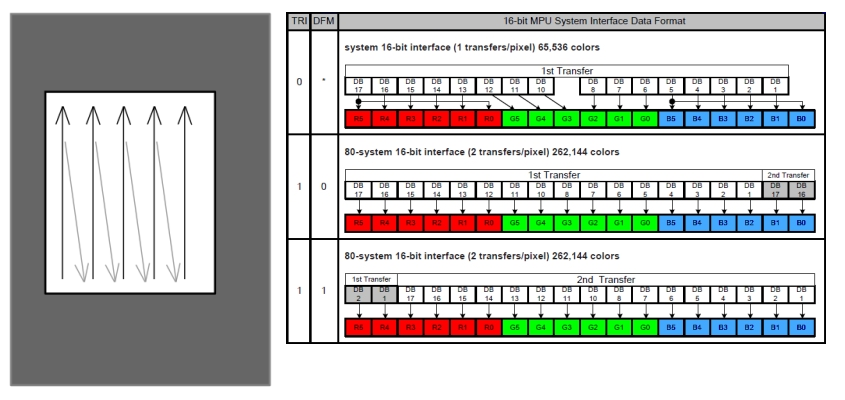
As it turns out, one of the formats supported by the LCD screen is a two-byte (16-bit) colour (5 bits red, 6 bits green, 5 bits blue). This means the palette will only take up 64*2 = 128 bytes. Every little helps!
Next I needed to convert each image into a series of RLE value pairs: instead of listing the colour of every single pixel, we give the device a start point, and end point, and tell it how many pixels – and of which colour – to display.
So a bitmap of, say, rainbow stripes might be described as:
- 20 pixels of colour number one (red)
- 20 pixels of colour number two (orange)
- 20 pixels of colour number three (yellow)
- 20 pixels of colour number four (green)
- 20 pixels of colour number five (blue)
- 20 pixels of colour number six (indigo)
- 20 pixels of colour number seven (violet)
So if we tell the device to start at a specific pixel, and that we’re going to flood fill an area of 20 x 7 pixels, then streamed this data into it, we’d end up with a perfect striped rainbow.
Exactly the same approach is used to draw more complex shapes. Except working out how many pixels and of which colour (and what those colour indices might be) would be a massive job with some graph paper and crayons.
So I made an app into which I could load bitmap data, and it took care of all the tricky number crunching for me
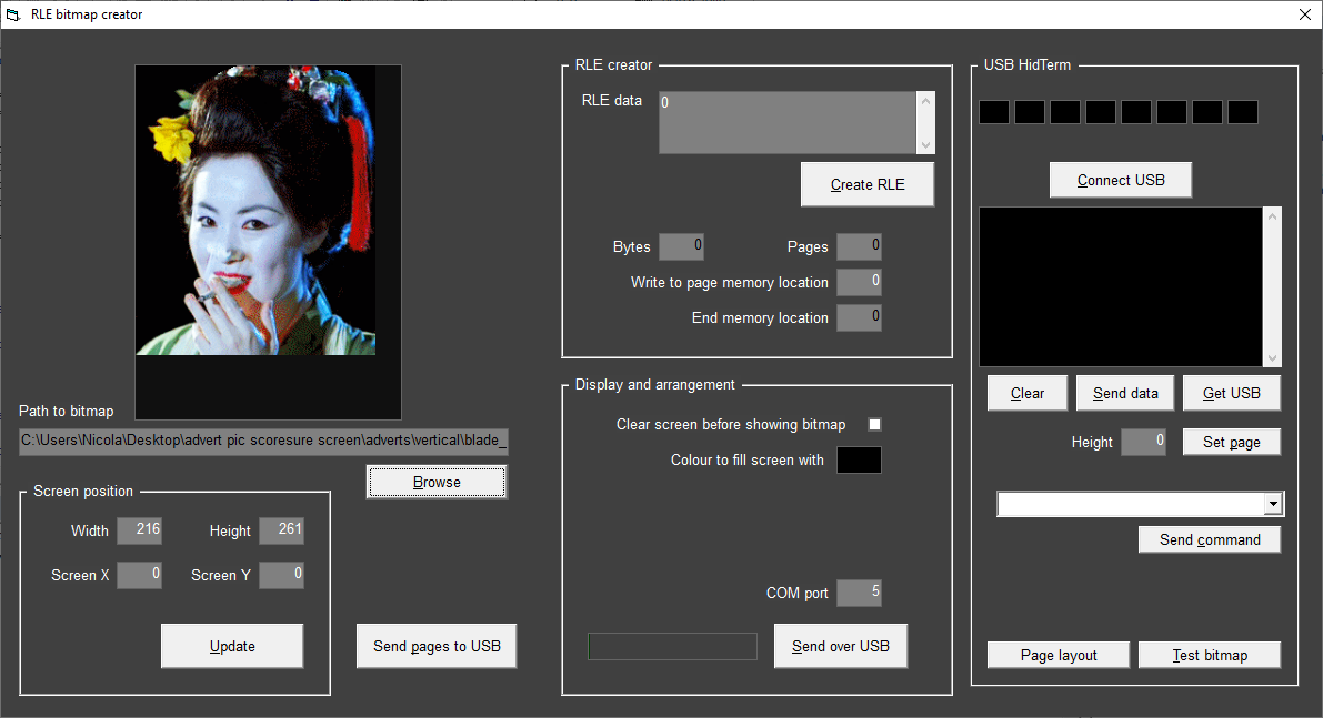
This produced a nice, easy to follow(?!) text file, and I simply entered the numbers exactly as they appeared in the file.
(ok, I didn’t sit and type them all in – I wrote another app for dumping data to the eeprom memory for me)

Now it’s just a matter of dragging the data out of eeprom and streaming them to the LCD display. So I did just that. And – amazingly – it worked!

It was really exhilerating to see actual bitmaps finally appear on the screen. Sure, things aren’t quite 100% right; each bitmap just lays over the top of the previous one, and there’s no way of positioning them on the screen yet, but that’s very definitely a series of bitmaps on that LCD!
Success can surely only be hours away……
So that happened quicker than I thought...
Wow. It’s only been a few hours since the last post, and here we are, with a working, scrolling, automatically updating miniature advertising hoarding for my 28mm cyberpunk skirmish game.
Yeah, sorry about the crappy music. It was only after I’d uploaded the video did I realise it had me and the wife talking over a film on TV (I think she was watching Wuthering Heights). No matter how horrible you think the music, is, honestly, it’s better than listening to our banal whitterings.
So – there we have it.
A little QVGA screen that I can connect to my own app and upload bitmaps to. I can change the delay between bitmaps, the number and order of the bitmaps, and whether or not the screen turns off between images (you can see this in the video – sometimes you can watch the bitmap being drawn across the screen, sometimes the screen goes off, it draws the bitmap in “darkness” and then switches on with the image complete and in place).
Now I just need to head over to the laser cutter and make some kind of enclosure to make it look like a billboard. Or maybe hack at the free gift this week and 3d print one?
Creating an enclosure for the LCD screen
While it appears quite slim, once removed from the original enclosure, the LCD is about 3mm this, it’s still stuck to a PCB that’s nearly 2mm thick, and on the back of that there are some surface mount components that increase the thickness again by another 3mm or so.
All in all, it’s going to need a decent sized enclosure, not just a cardboard facia to look anything like an actual billboard.
My resin printer is currently churning out vampires for my other diorama (https://www.beastsofwar.com/project/1511034/) and the Tronxy/FDM machine was recently moved across the workshop and still hasn’t been set up fully with a flat, level bed.
So I thought I’d burn some wood and see how that looked!
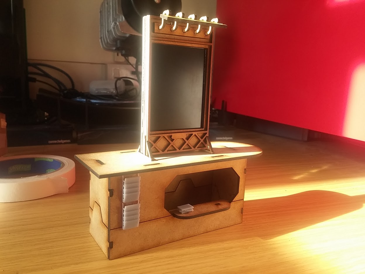
And, in short, I think with a lick of paint, I might get away with it. I’ve been laser-cutting anyway, to create a mix of high- and low- rise cyberpunk buildings. This one, for example, is a newsstand.
I thought I might make a series of newspaper/magazine spoof headlines for it (Agent Brown Ate My Hamster – that kind of thing). Seeing it now, I think I probably need to make a version in landscape as well as portrait.
But that’ll require a new firmware. Maybe I can tackle that tomorrow….
Now available in portrait or landscape
I’ve been pretty busy with a couple of other projects in recent weeks (and one particular one which is a real black hole for hobby time) but after seeing some awesome satirical adverts on a Facebook group, I decided to update the firmware on my cyberpunk city billboards.
Now they can be used in either portrait (upright) or landscape (sideways) orientation.
A guy called Matt came up with some brilliant spoof adverts, so I wrote some tools to convert his images into the appropriate ones and zeros and stuffed them into the onboard eeprom. The result was pretty impressive.

So I added a rechargeable battery (it was a left over Samsung phone lipo) and an on/off switch and sent him a cryptic message over the intertubes – send me your address and I’ll send you something cool for your adverts.
Amazingly, he did. So I did.
His cyberpunk junk city looks pretty impressive. And under muted lighting, the advertising billboard looks just great!
I’m calling this one done. Time to move on to the next project…..