


![NO Weekender Or Cult Of Games XLBS This Weekend [Updated]](https://images.beastsofwar.com/2026/03/No_Weekender_and_XLBS_this_Weekend-225-127.jpg)


Tuscany Hill Village Terrain Build


Recommendations: 1109
About the Project
I started this project some time ago. It's a slow burner. But I've decided to turn it into a project so that I have a reference point but also to get some help along the way. This is my attempt at trying to recreate an Italian Hilltop village in 15mm....
Related Genre: Historical
This Project is Active
Filling in the gaps
Firstly, good news with the rock moulds – the No More Nails doesn’t melt the foam base and does hold the plaster rock to the foam. However, as the foam base is curved, straight strips of plaster rock aren’t going to stick well without leaving gaps, so I need something to fill these in.
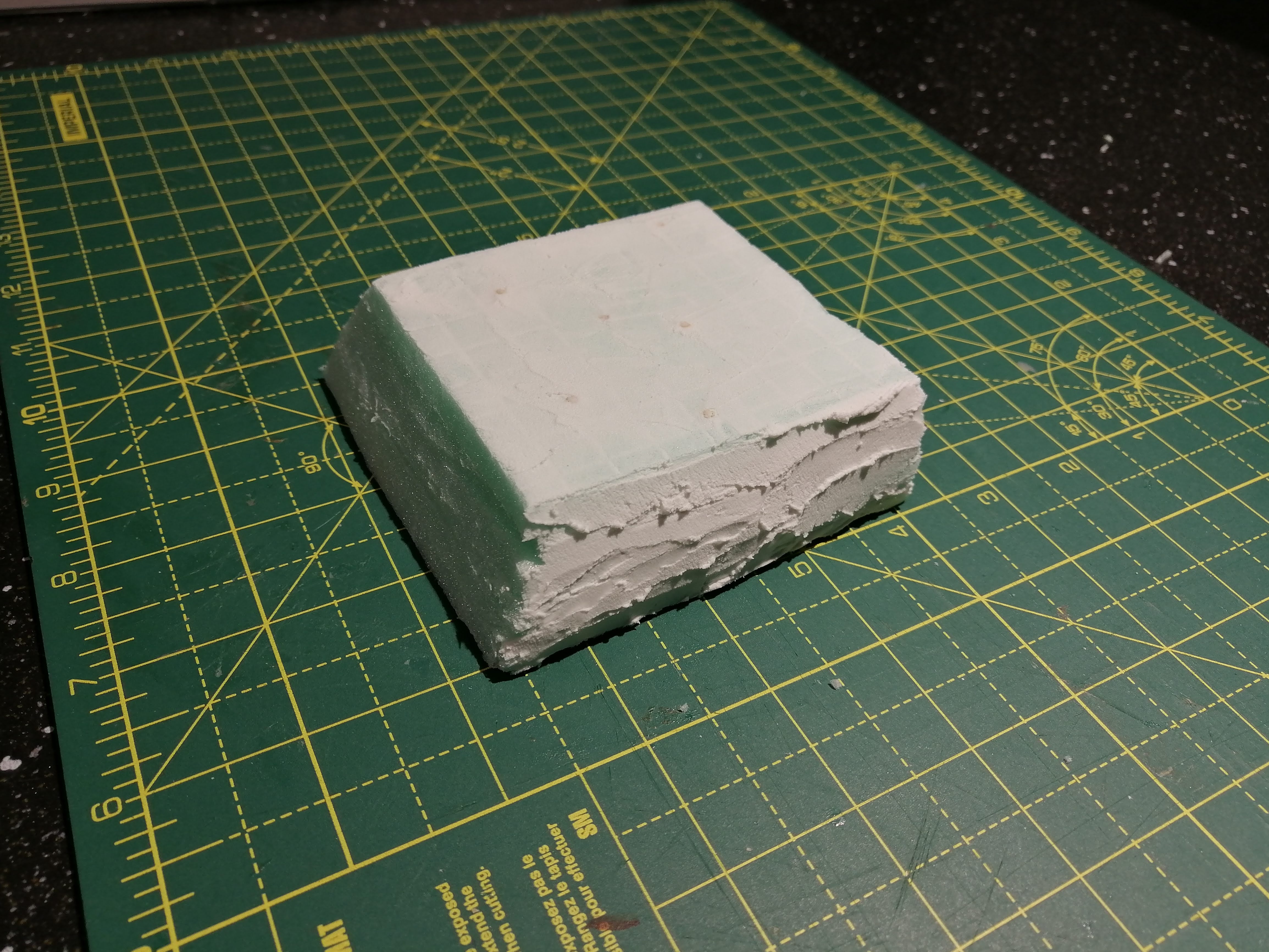
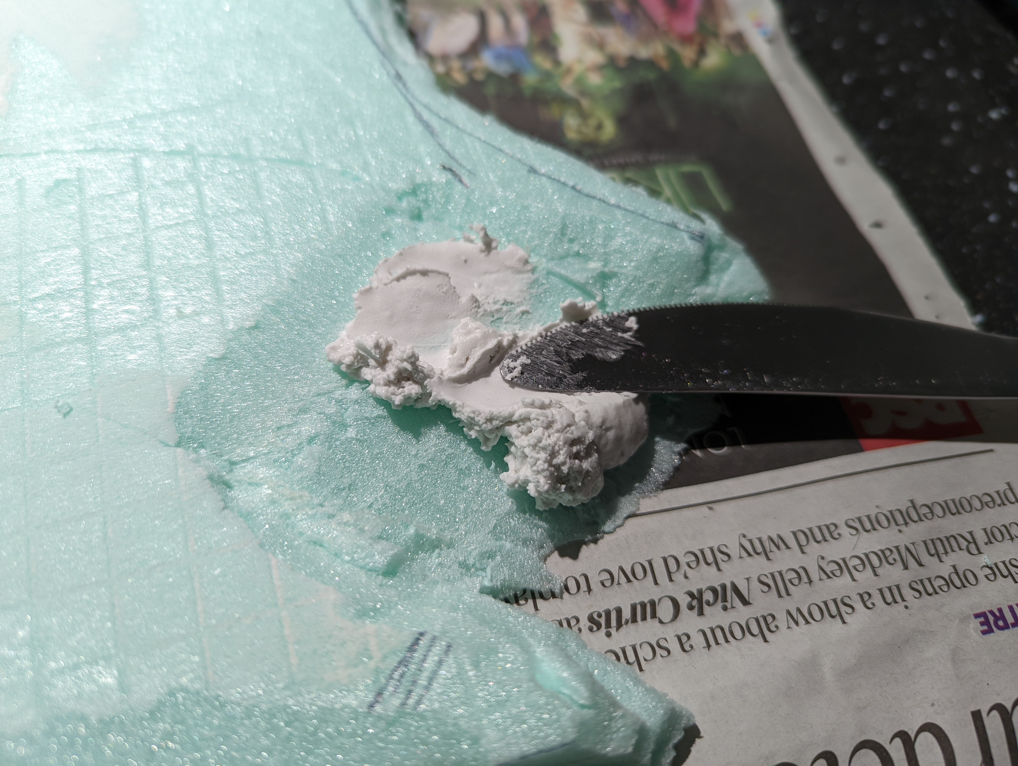
After hunting around, I see that modelling compound is a thing so I thought I’d give it a go. I picked this up on ebay

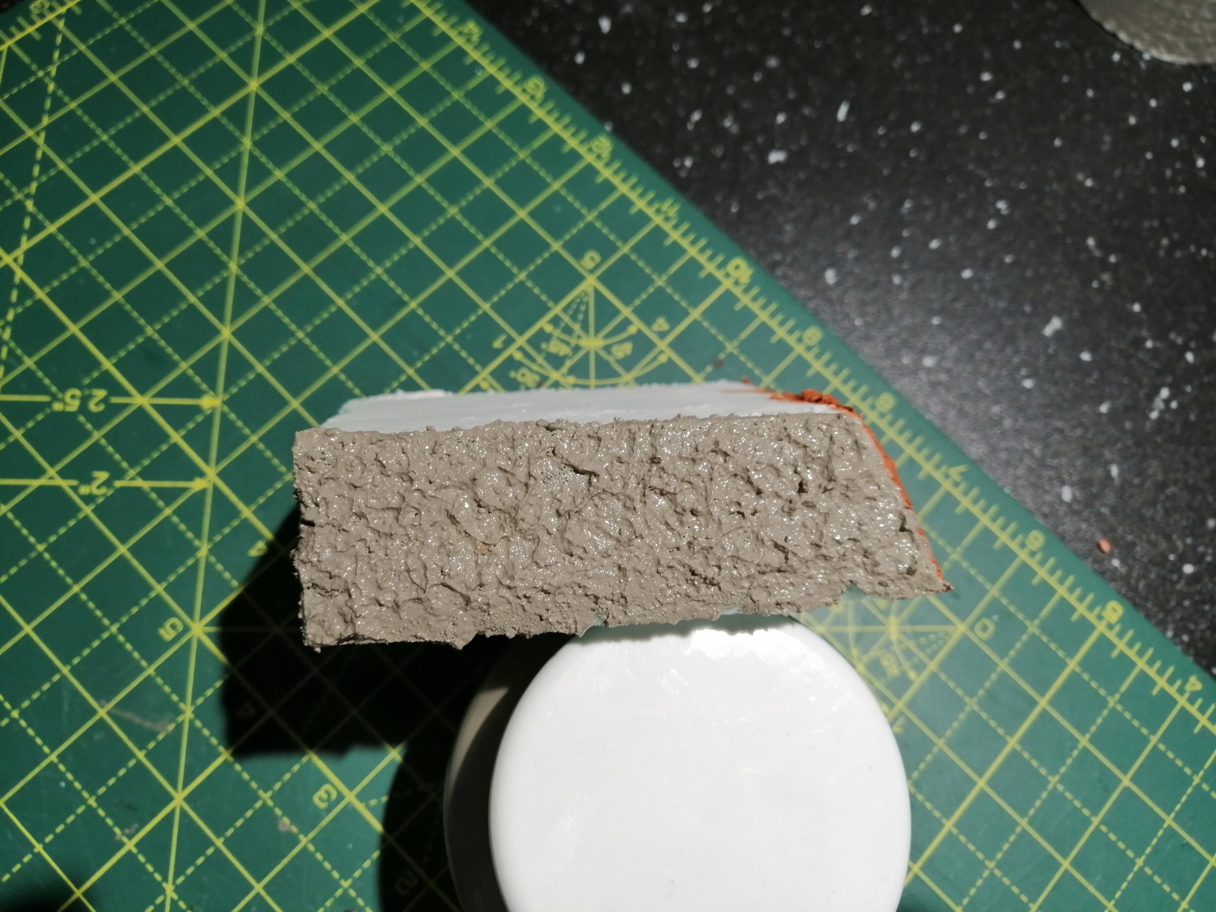
It mixes into something like a lumpy, cottage cheese. It also dries reasonably quickly but stays ‘damp’ for some time allowing a degree of modelling to be applied.
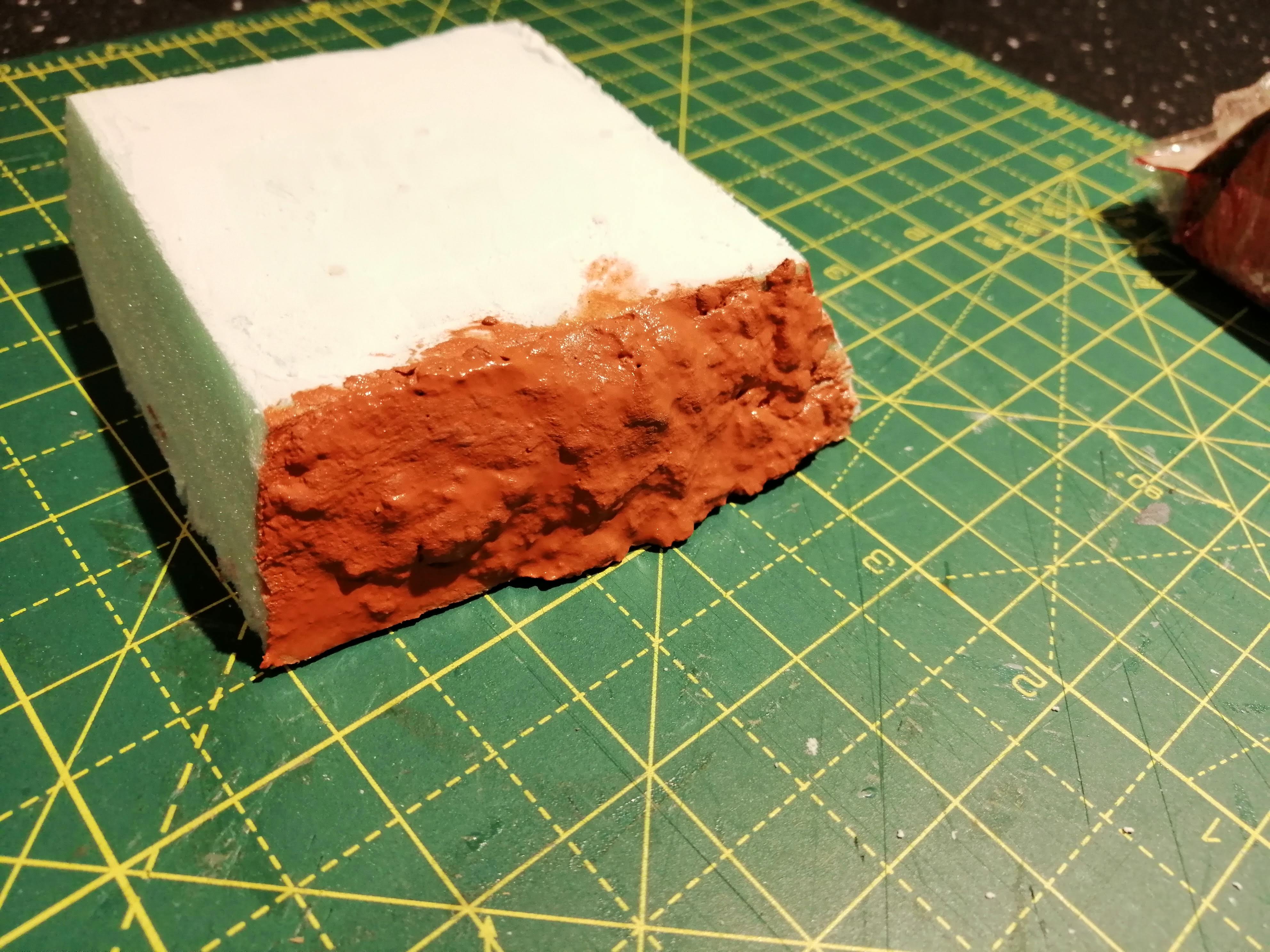
I’ve applied it to my test piece (below) and it dries into a grey mix. While it dries quickly at first, it did take a good 24 hours to fully dry. Even then, it’s still not fully hard.


Once dry, apart from being a little soft, I think this will work well. I’m planning on most of this being flocked so it’s really there to just provide substance.
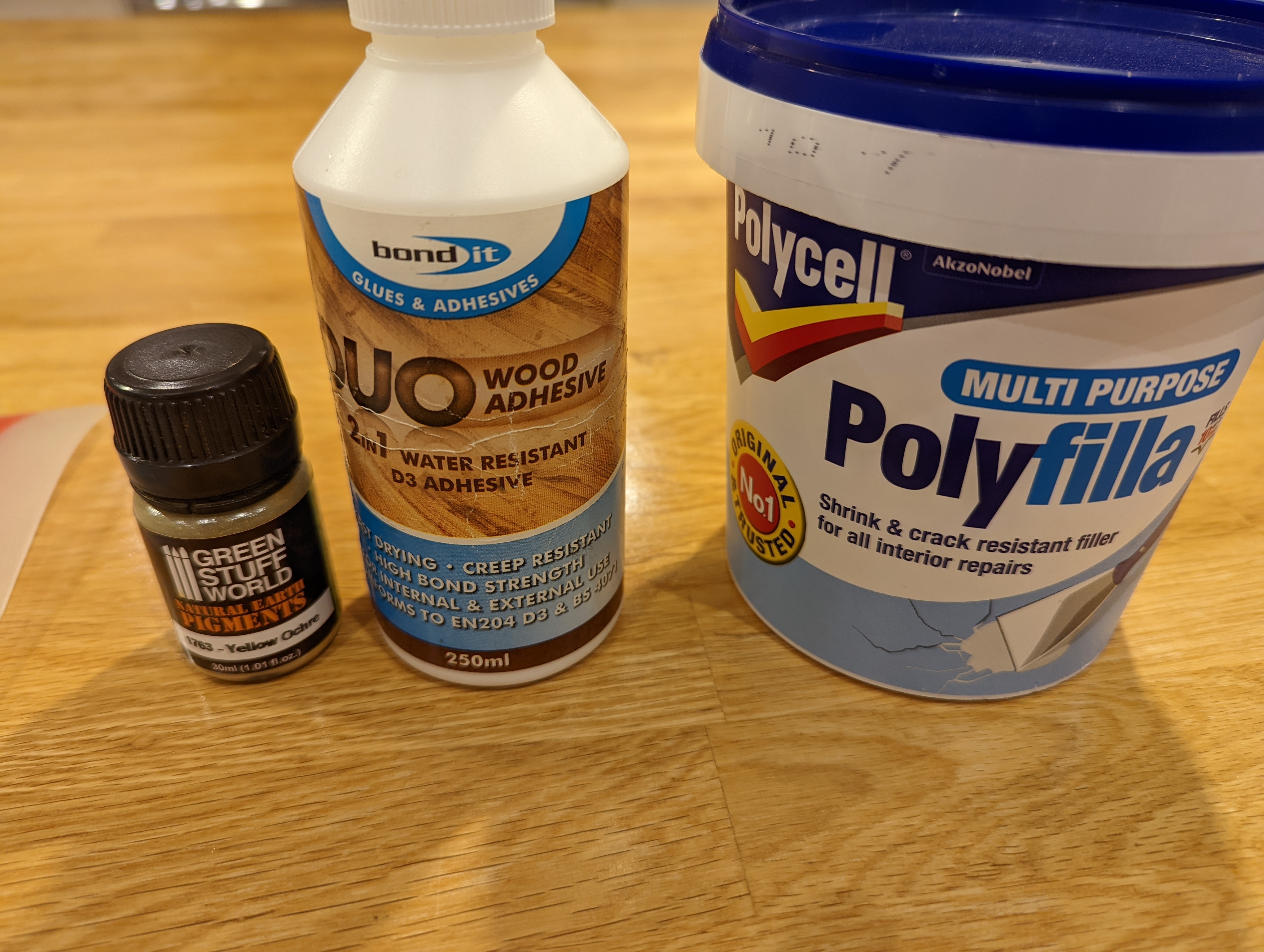
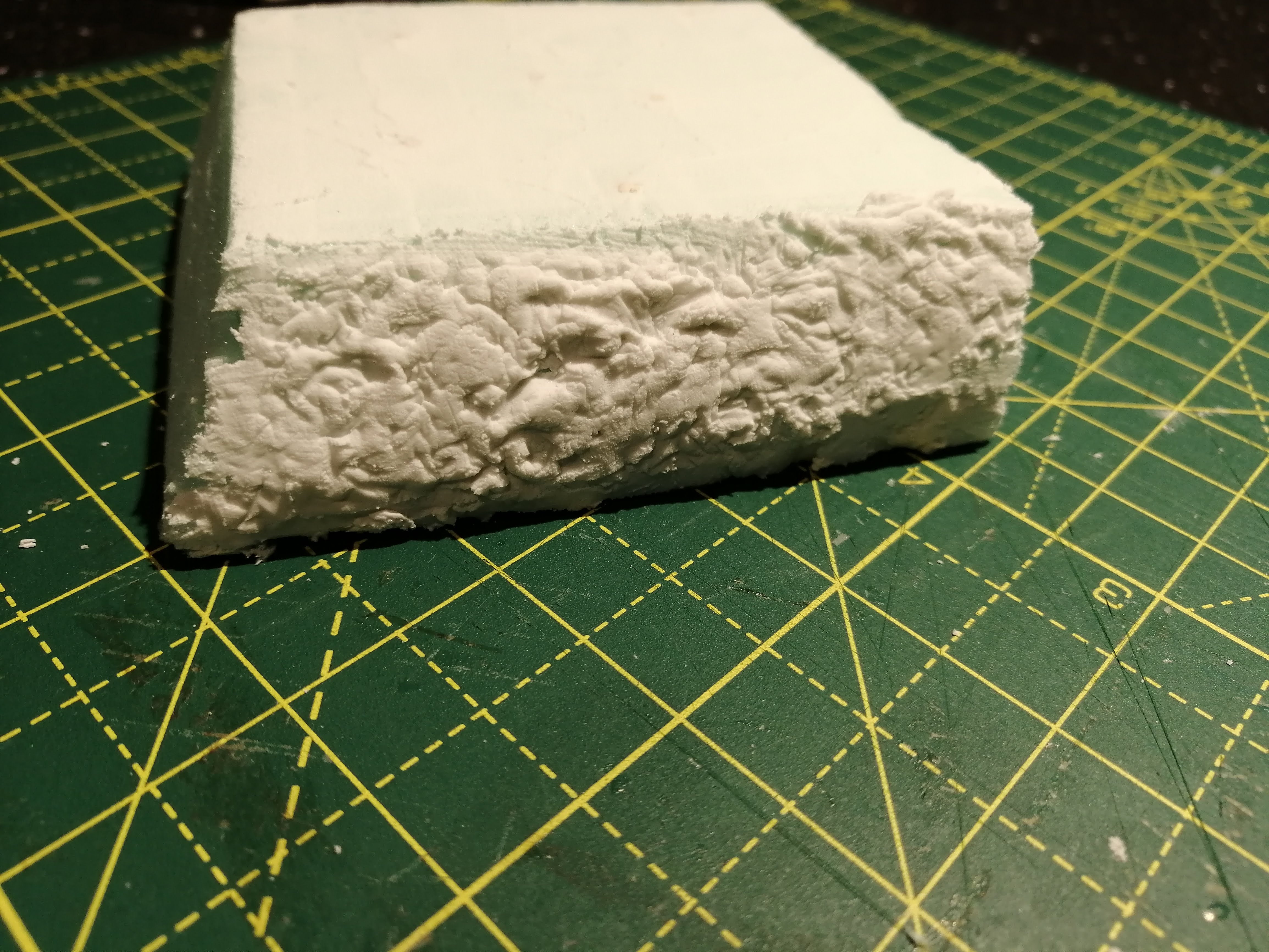
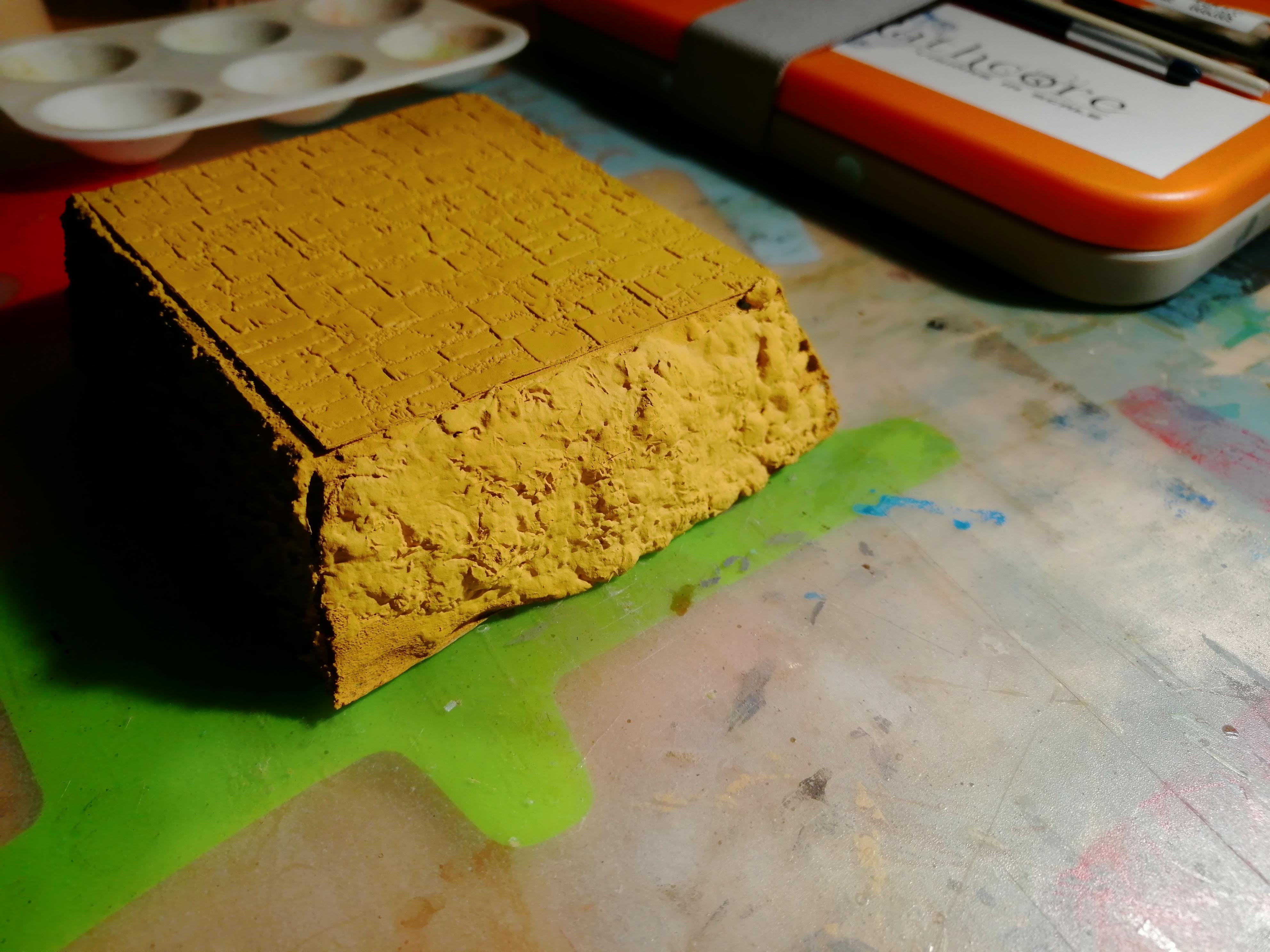
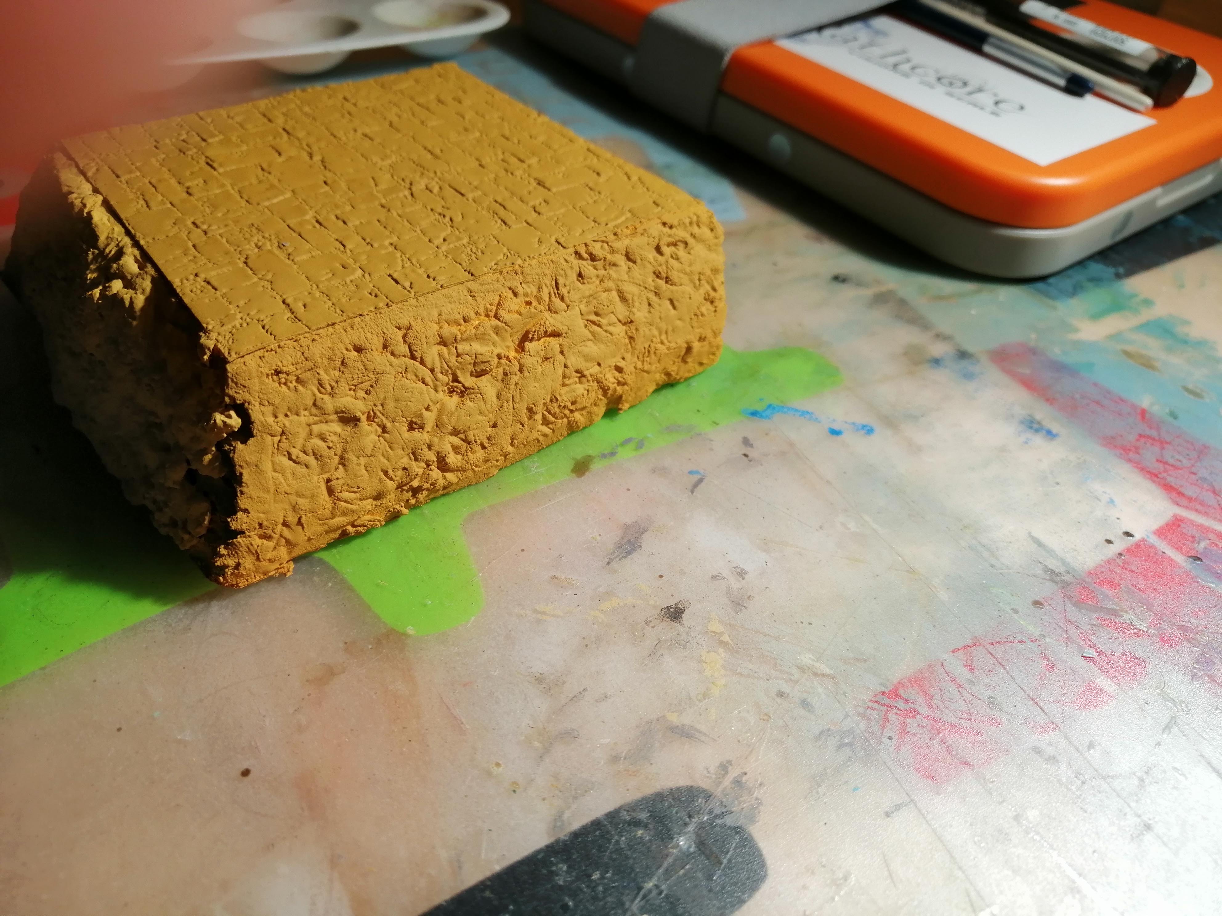
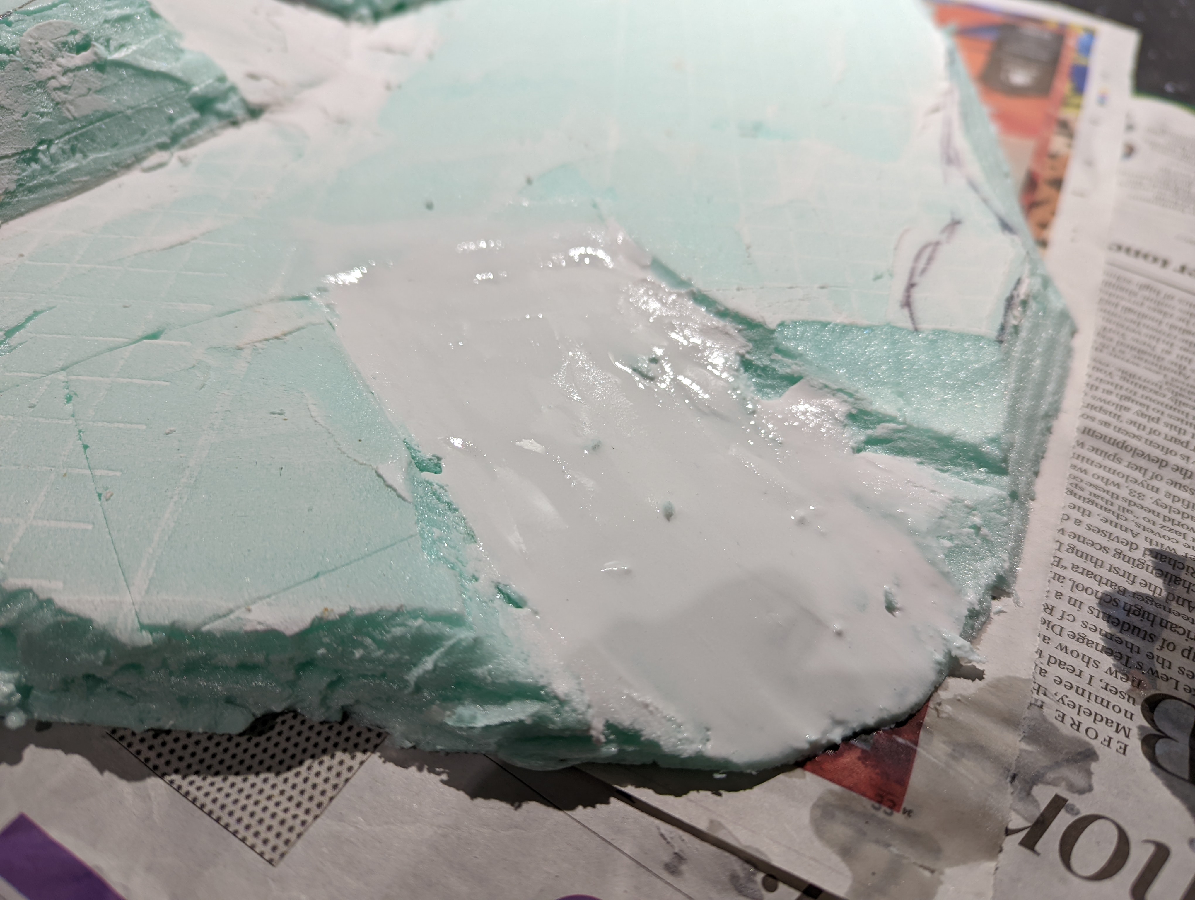
To address the softness and to make it look a little less lumpy, I’m going to try a pva and polyfilla mix, watered down a little. While I’m at it, I’ll mix in some pigments to see if I can colour it at the same time.
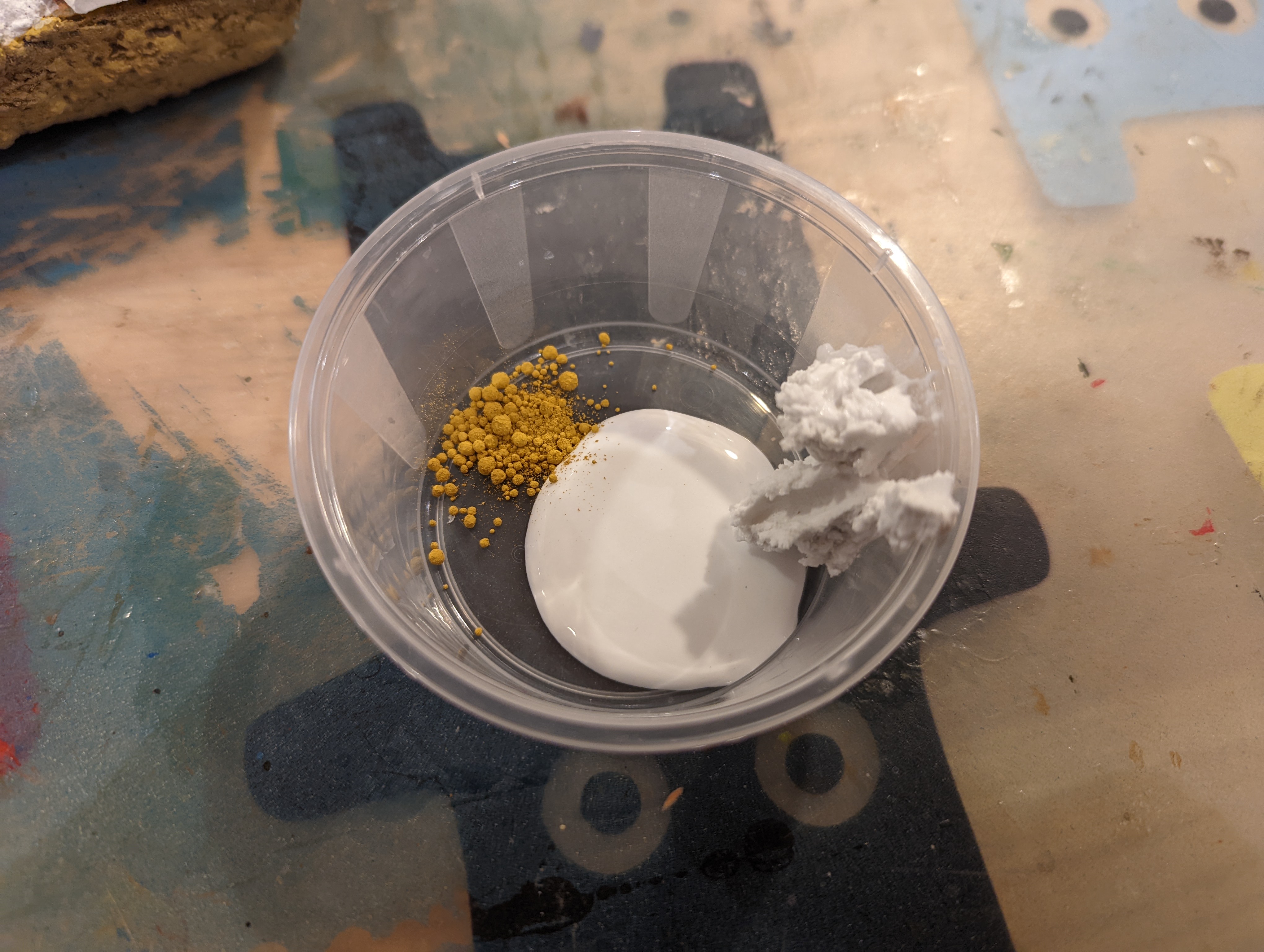

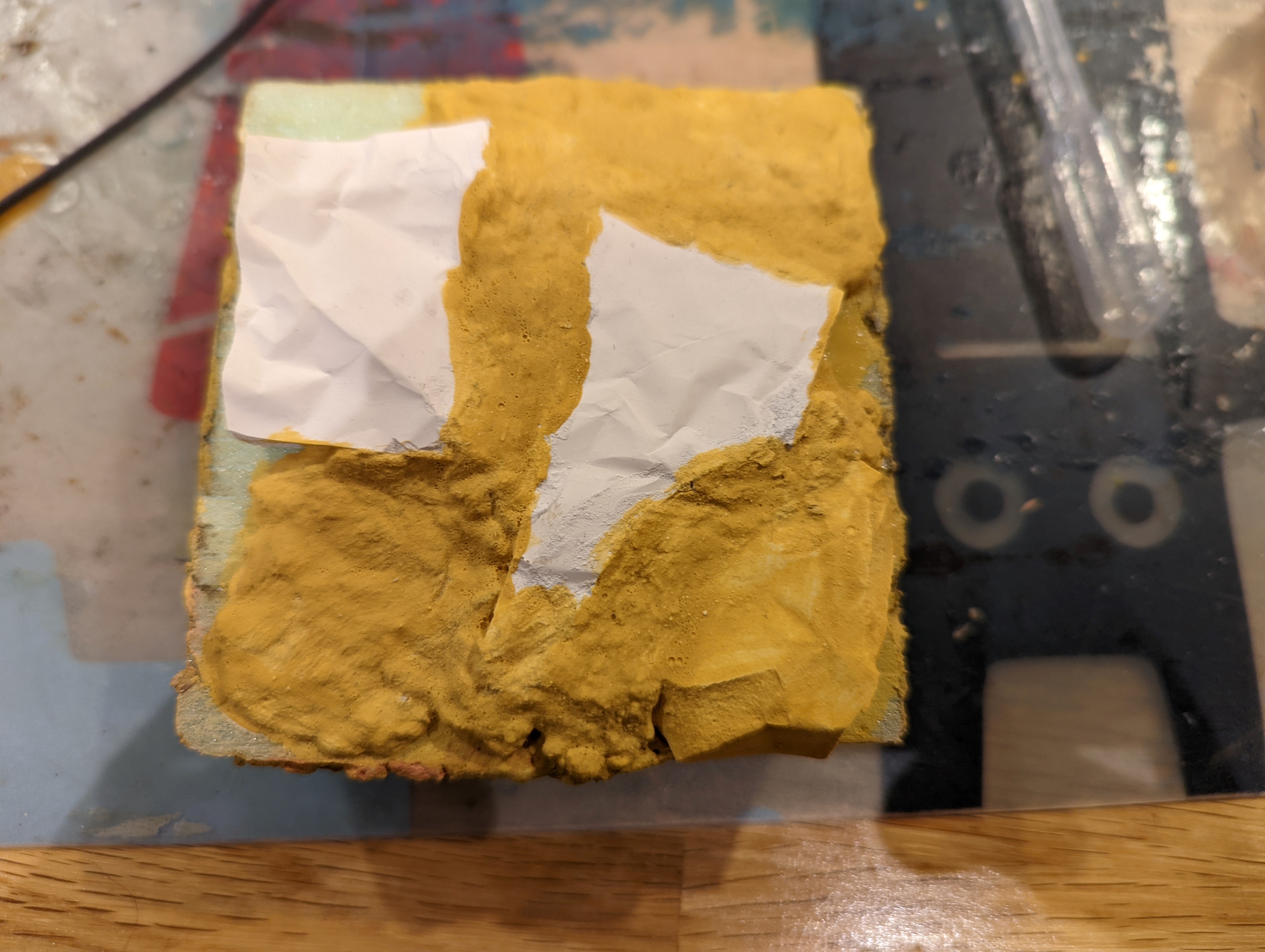
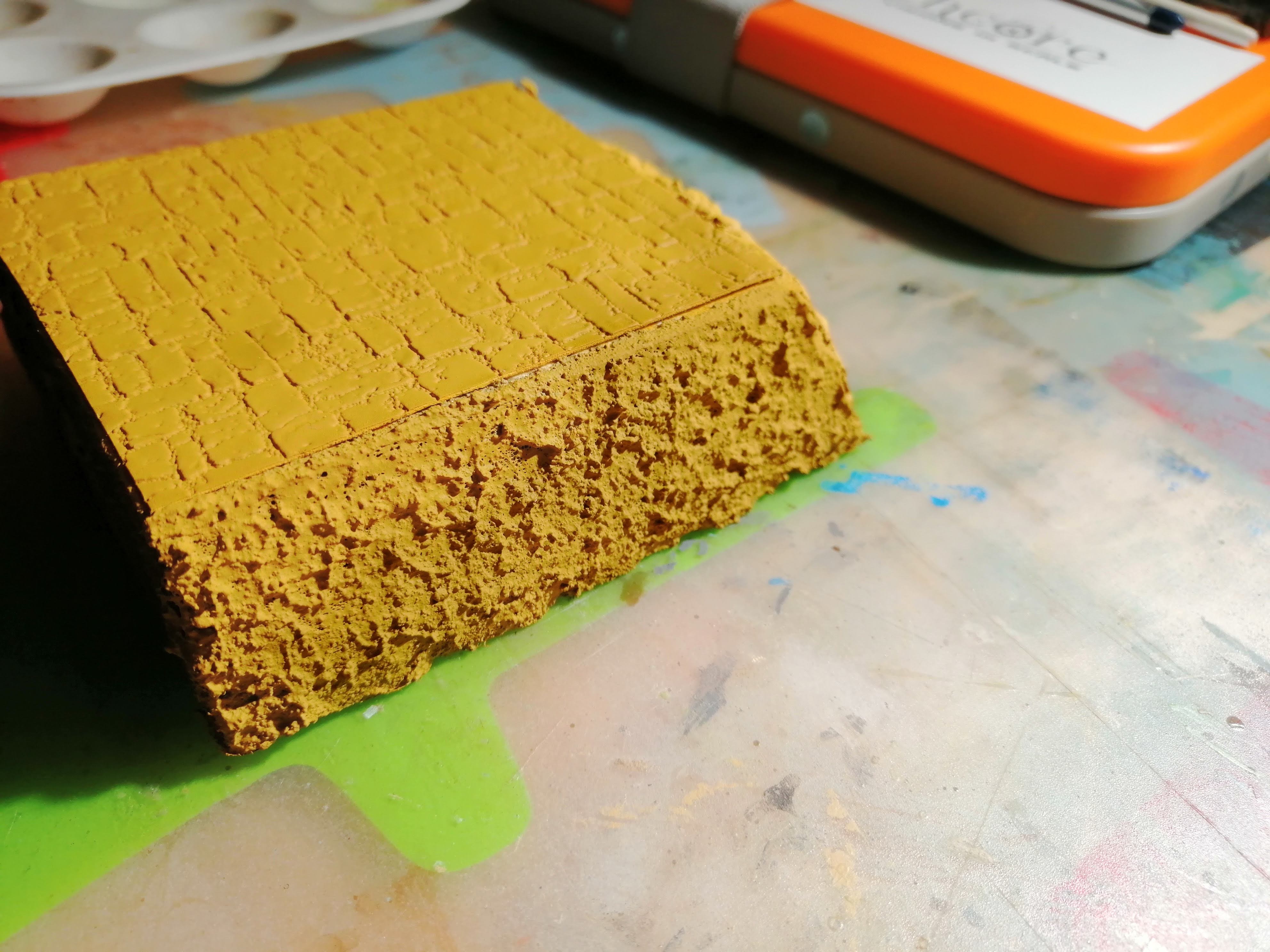
Once dry, this has certainly hardened the top surface a little (not fully, perhaps adding more polyfilla would help). It has also provided a slightly smoother surface.
The colour is a little strong for what I’m aiming for, so I will have to look into getting the right pigment, but it certainly works. I now have an approach to modelling the sides of my hill.
Next job is to start gluing on the rock moulds to the actual hill that I have crafted.
Casting my own rocks
Not happy with the previous attempts at trying to get ‘rocks’ I’m going to try to cast my own. I’ve never tried this before, but as plenty of others have, how hard can it be?
I did look at some of the various moulds that you can buy for casting but these were quite expensive and as I’m unlikely to do this again, I decided against it. All I bought was a bag of plaster on ebay.
Creating my own mould
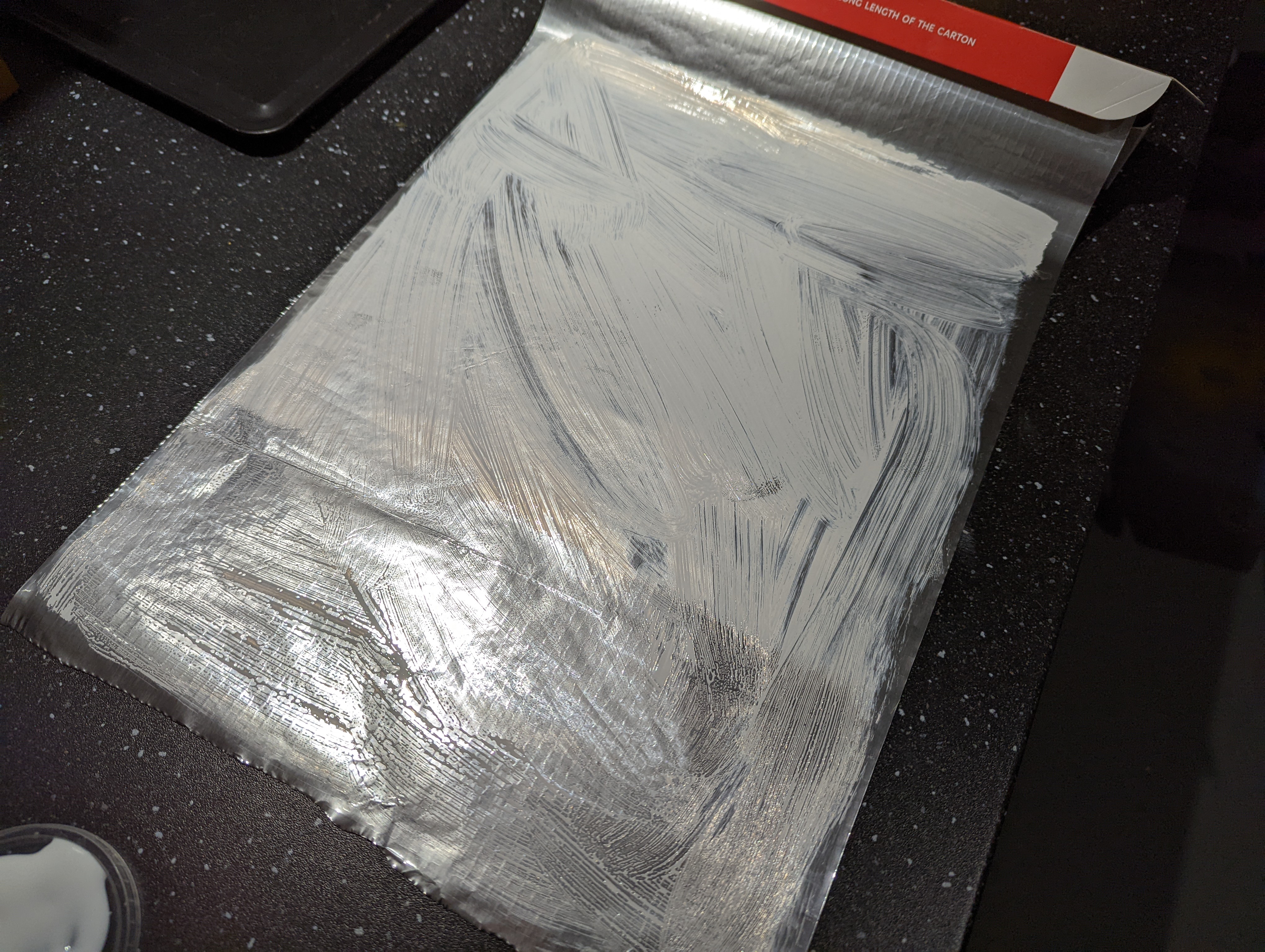
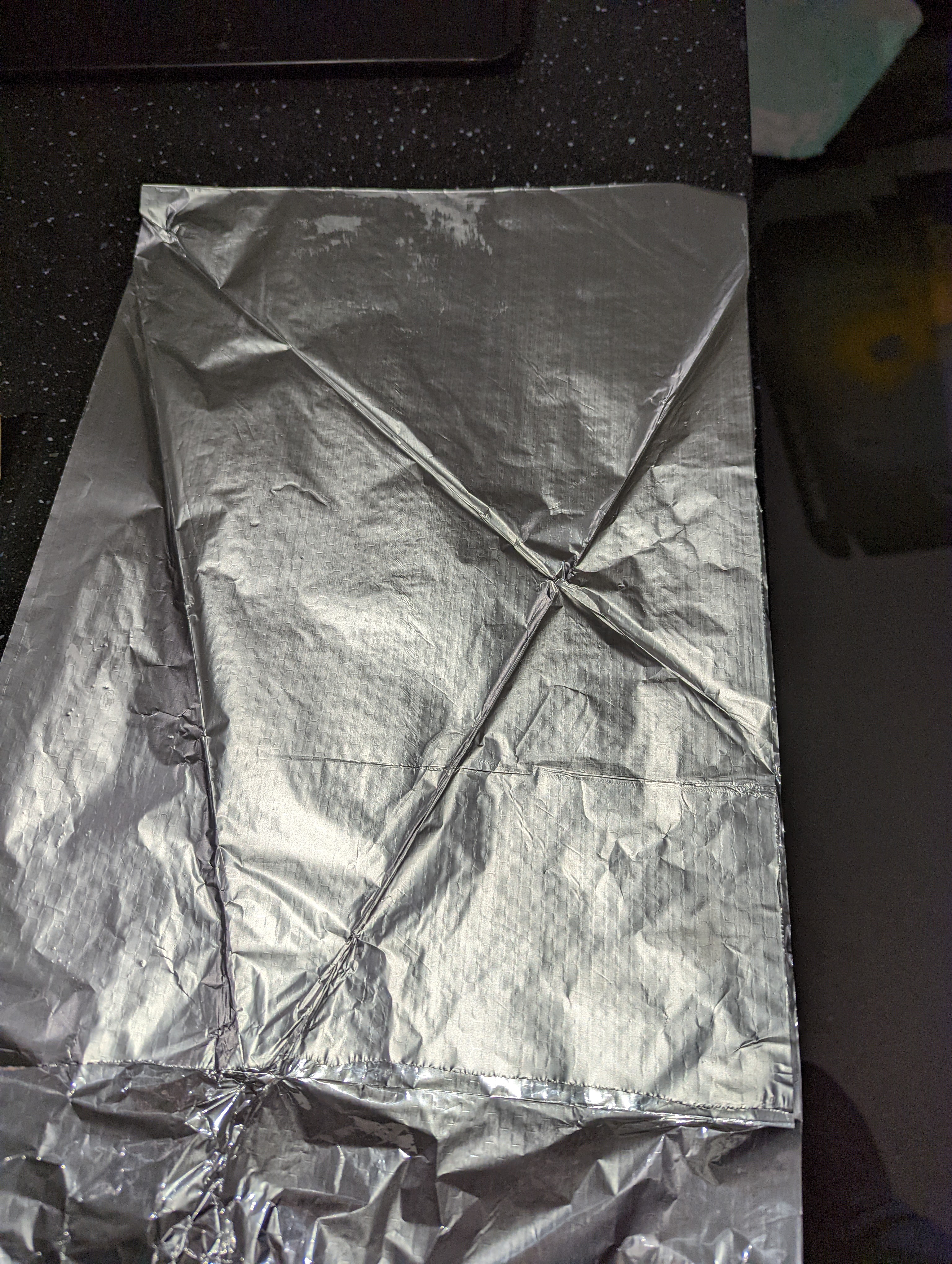
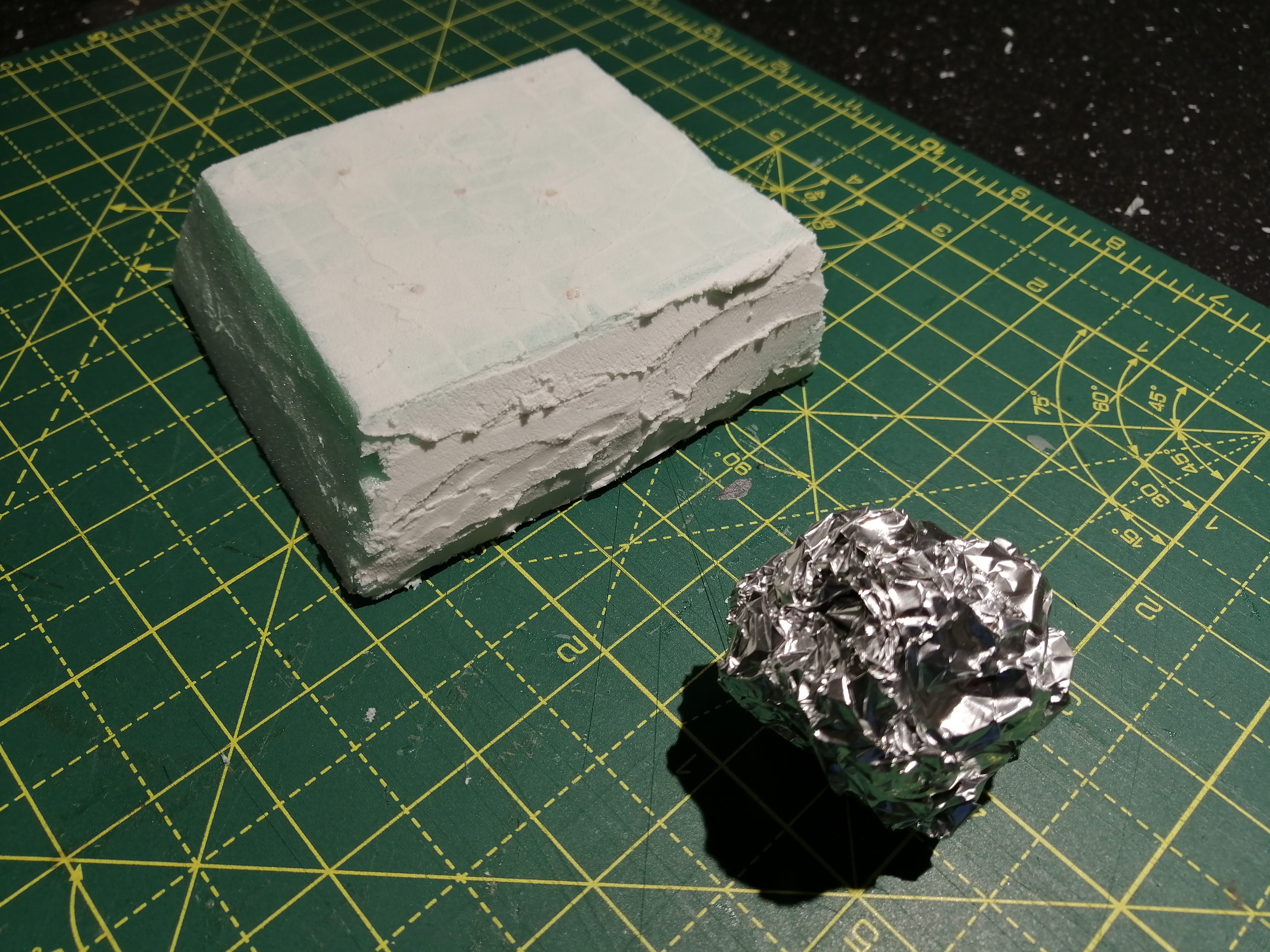
Trying to find a cheap alternative for a mould, I came across the use of aluminium foil. Seemed like a good option so I gave this ago. First up, I layered 5 sheets of foil on top of each other and used PVA to glue each layer together. This should create a bit of rigidity once the plaster gets poured in.
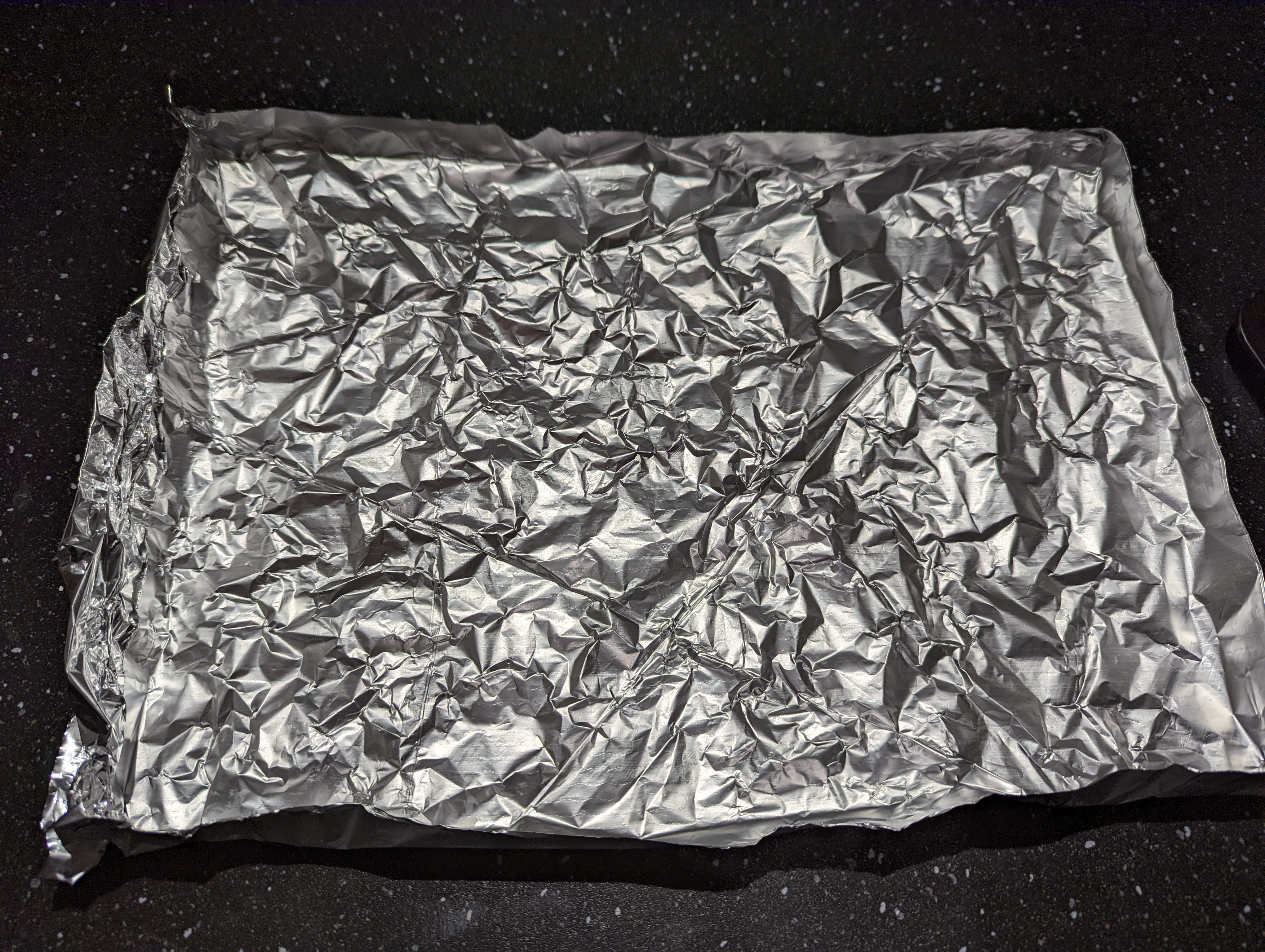
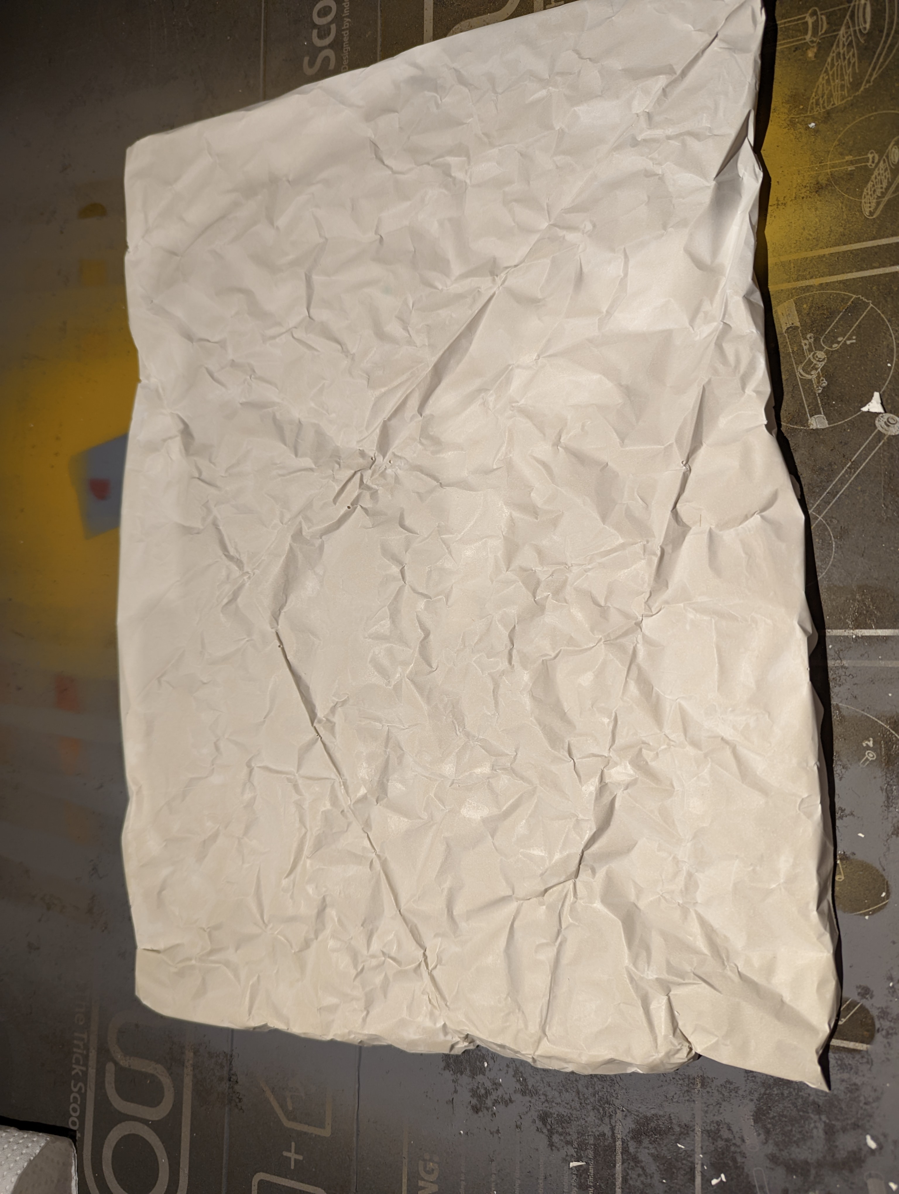
Once the PVA dried, I put some folds into the foil to try to create the deeper rock recesses you sometimes see. I then scrunched it up a bit and folded the edges up to stop the plaster running out. I then mixed up the plaster and poured it in. You can see the steps below.
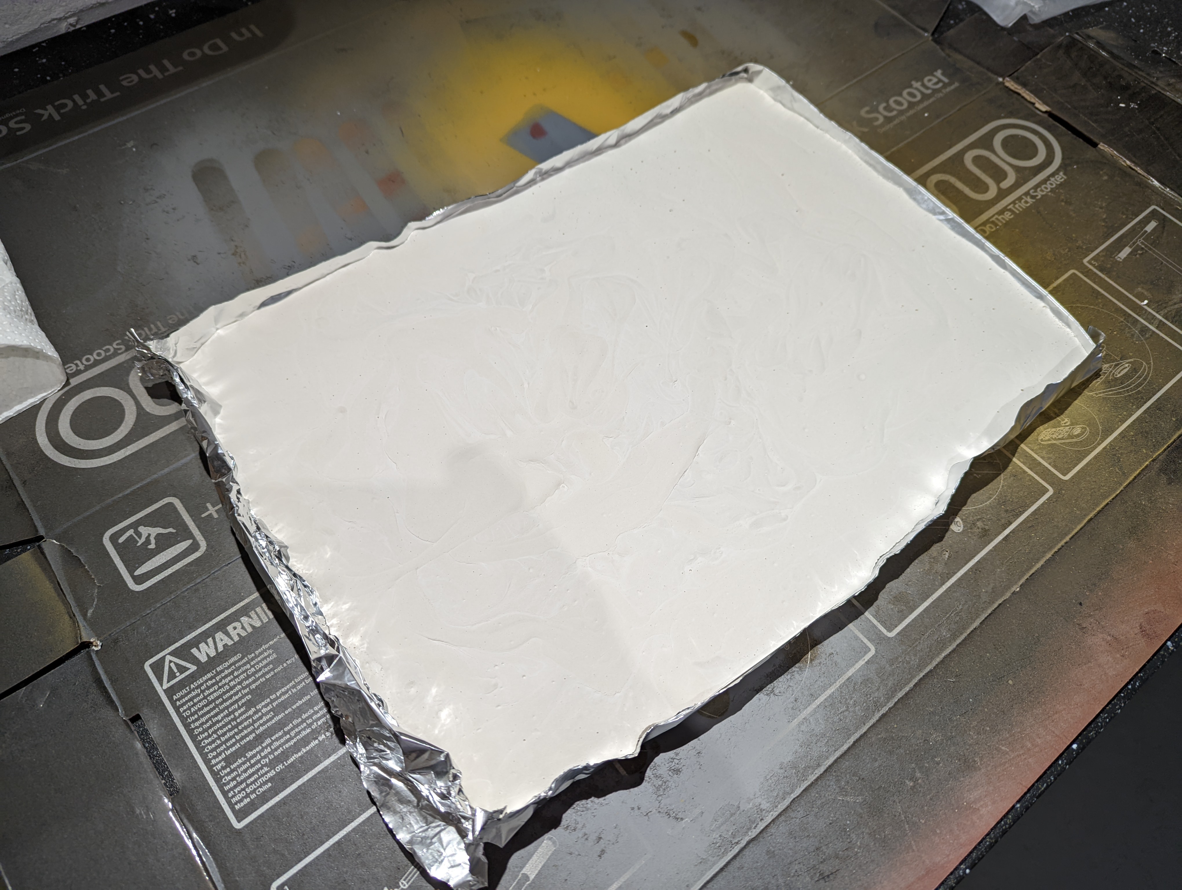
24 hours later, I removed the cast from the mould. Here’s where I realised my first mistake. When putting the folds into the foil, I stupidly forgot to do them in relief, so rather than cracks into the rock, I have outward facing ‘lines’. However, it doesn’t look too bad and this will need to be cut up, so probably not as noticeable.
My second mistake was making the pour quite thick. In places, the casting is around 2cm thick, which for the scale I’m using might stick out a little too far…
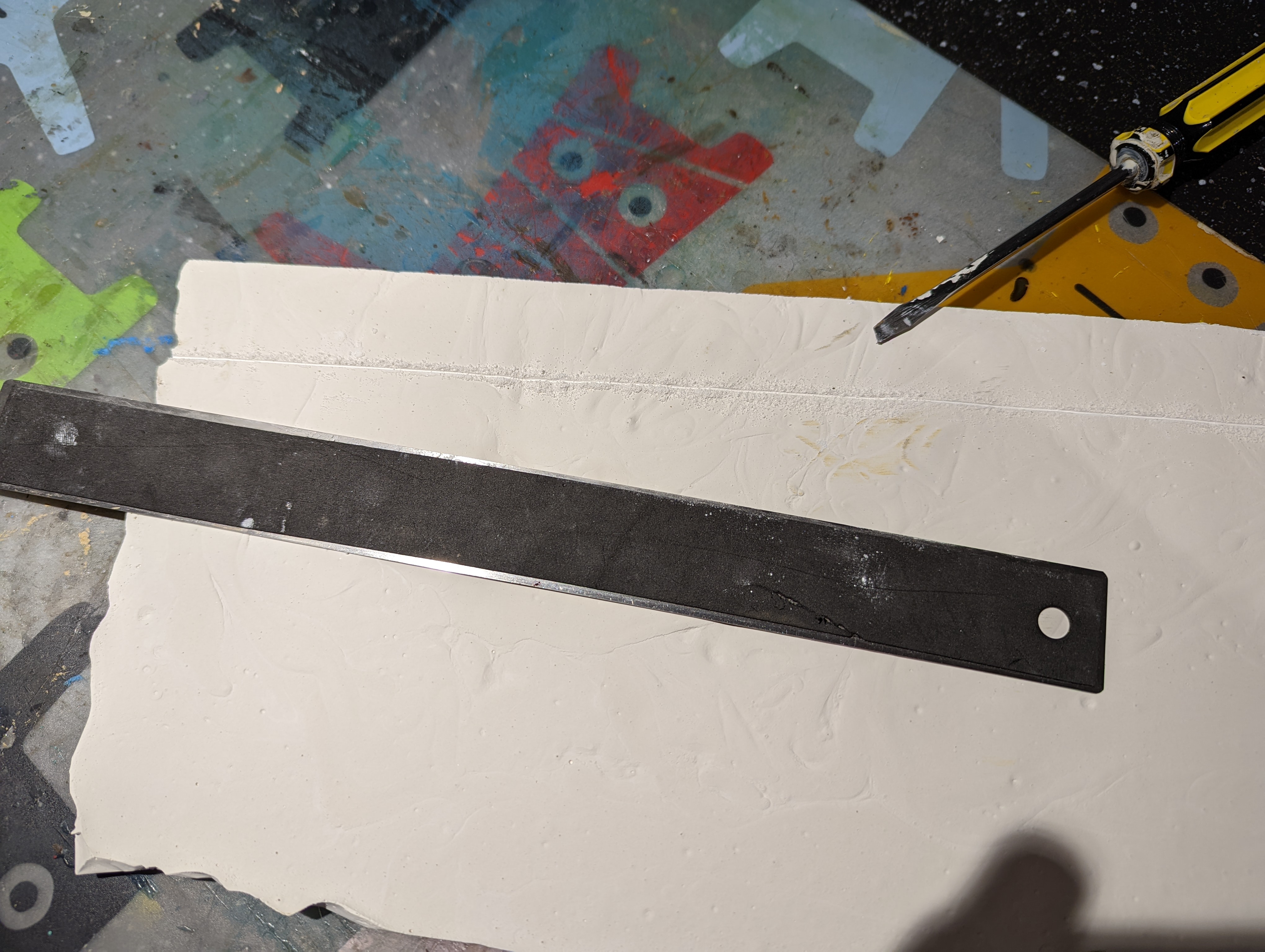
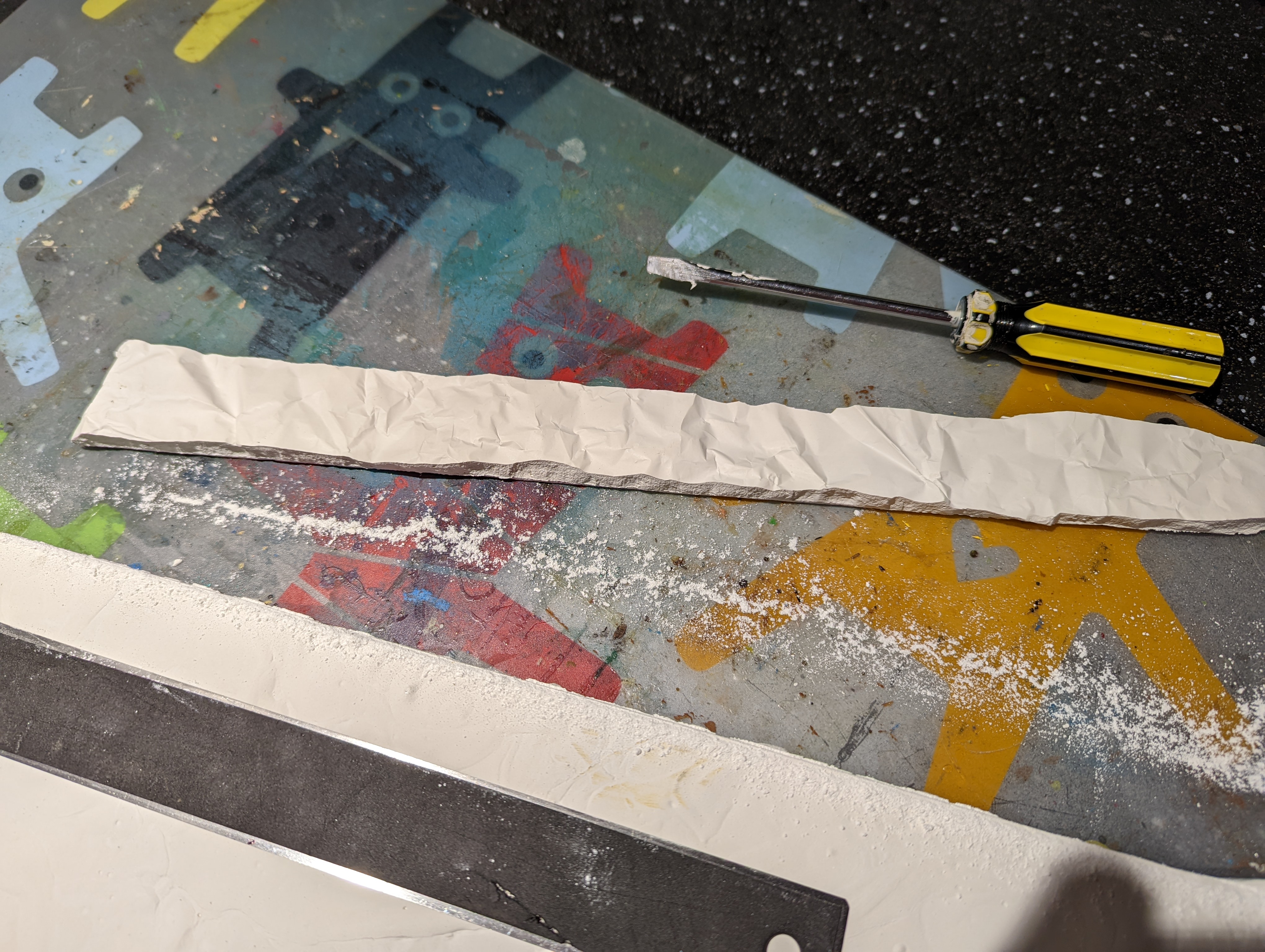
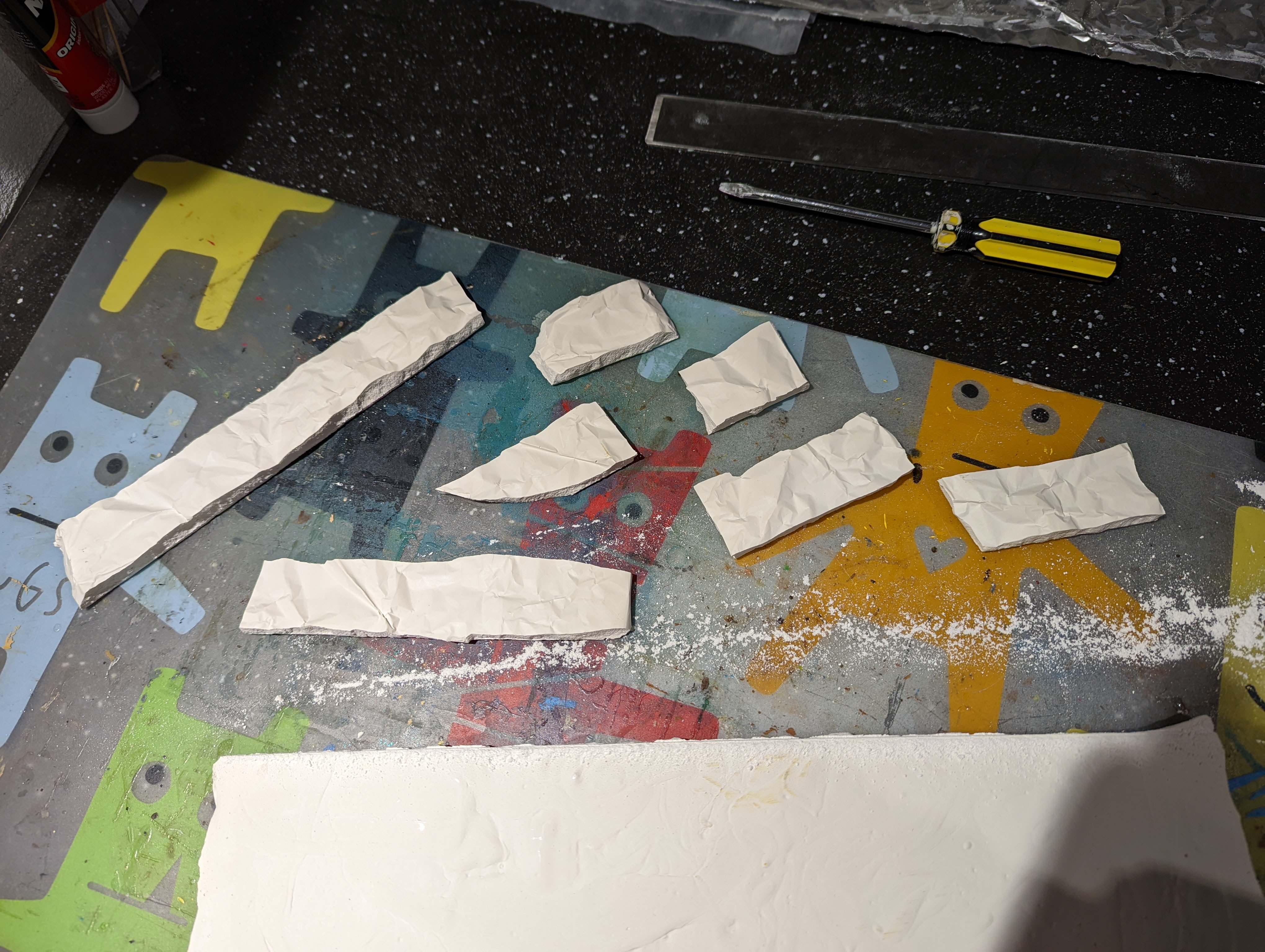
The size of the casting is a bit bigger than A4 so needs to be cut down to size. This was hard work, given the thickness and achieved with a metal ruler and a flat head screwdriver to score the plaster. I tried a knife but got worried I was going to remove a body part.
Each strip is between 1 and 2.5 cm high, to align with the different parts of the base model. I’ve then broken each strip up into smaller parts that can be glued to the foam base.
I now need to stick this to the foam base. Not knowing the best way to stick plaster to foam and with the risk of some glues ‘melting’ the foam, I need to put a test piece together. I also need to work out how to fill the gaps between the rock castings once in place, so this test piece will fill that role as well.
For the glue, I opted for No More Nails. From the blurb on the back of the tube, it doesn’t suggest that it might cause problems.
It took a little while to dry but so far, seems to have stuck the castings to the foam without any damage. I now needs to fill in the gaps with something.
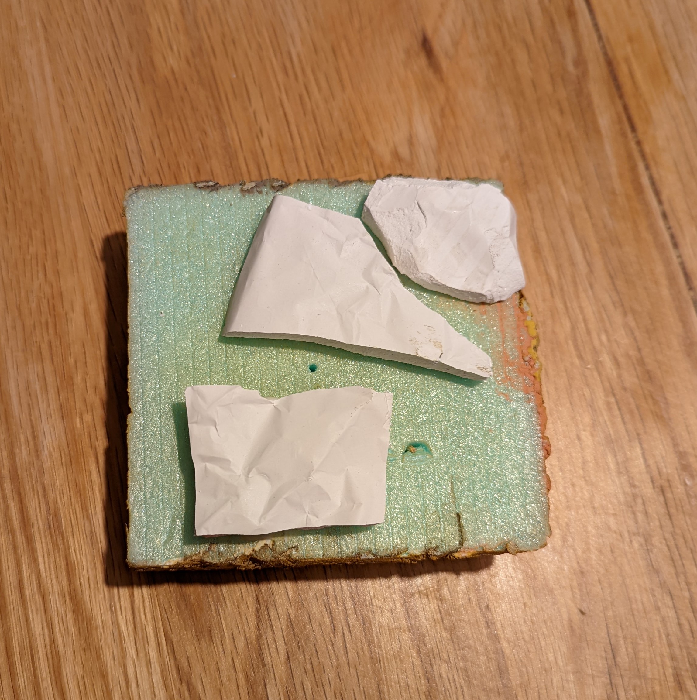 Off cuts of the casting stuck to my test piece
Test options for the base
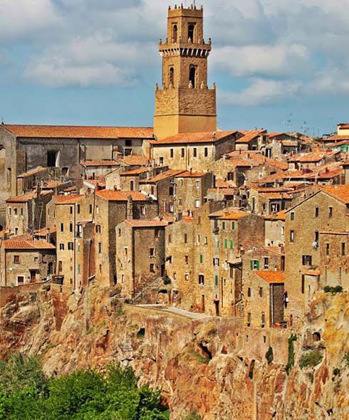
With the base now carved to the right size, I want to start creating the rock walls around the edges to create the ‘hill top’ feel. Here’s a good example of the sort of thing I’m aiming for.
I’ve got a few options for this and I think I need to test this out first before applying it to the whole model. So I’ve quickly glued together a test model.
Option 1 is to apply the air drying modelling clay around the edges. This has the advantage of being slow drying and will allow me to actually model it into the shapes that I want. I’ve also seen some useful videos where this has successfully been used to create river beds or muddy roads for dioramas, so is an option.
Option 2 is good old polyfilla. I’ve used it loads before but perhaps not in this quantity but I at least know its properties.
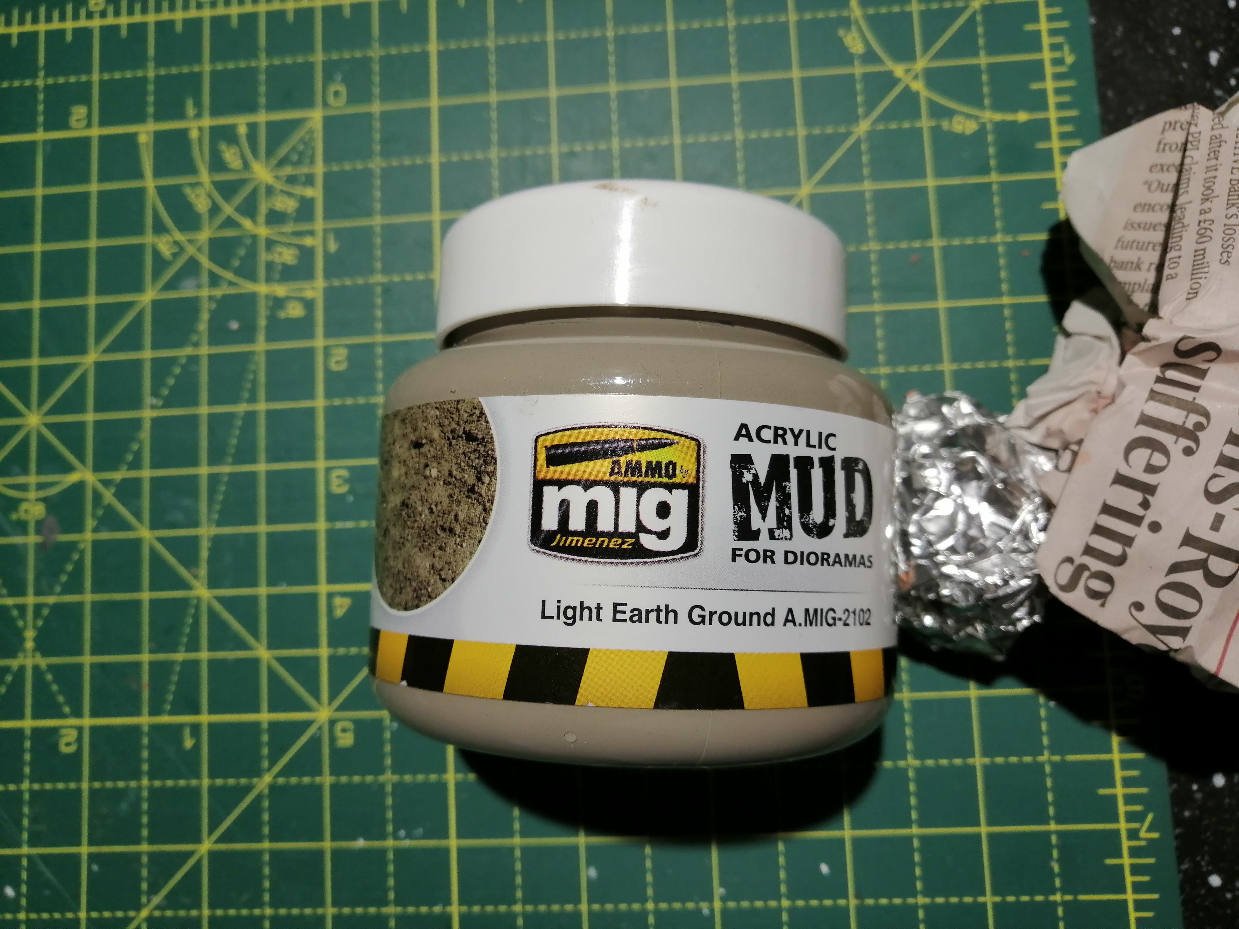
Option 3 is some MIG acrylic mud. I’m thinking that its texture could look rock like and it will stick to most things.
Below is option 1 after being applied. Getting it to stick to the foam was a problem but application of water really helped.
Option 2 and the polyfilla went on fine (as I was expecting) and then I used some rolled up tin foil to create a ‘rock’ texture by rolling it over the top
Option 3 went on easily and clung well to the foam but is difficult to ‘sculpt’.

Once dry, I gave them all a spray with the primer I’m thinking of using to see how they look. Here’s the results in order
The verdict?
The clay didn’t really stick too well to the foam and was already starting to come away at the edges. While there are probably solutions to this, it took a long time to apply and requires a lot of effort to sculpt to look good. Almost certainly skills and time that I don’t have. I’m also concerned about the clay flaking off which will annoy me. So it’s a no for the clay.
The polyfilla worked OK. It stuck well but the foil rolling didn’t look particularly convincing. I’m sure that this could be addressed easily but getting into the corners is a challenge. I’m going to call this my back up plan for the time being.
The acrylic mud stuck well and is lovely and hard. Problem is that it looks like mud which is not the look I want. It will also be expensive to cover the whole model with, so this is a no as well.
So where does this leave me? It leaves me having to cast my own rocks in plaster. So with the plaster on order, I plan to try casting for the first time and if they look good, sticking these to the outside.
3D Printing vs Scratch Building
This topic came up (I’ll say for ‘discussion’ :-)) on the uHH last week. I thought it was interesting as I’ve never considered it before, so I thought that I would put my thoughts here, particularly as I’m scratch building and 3d printing in this project.
Firstly, I guess the discussion was aimed at people who at least don’t try to scratch build and that technology is the first answer. I agree that not giving this a try is a shame and a big part of the hobby. I still remember my crude attempts at scratch building when I was young. But for this project, I’ve considered my skills and time as to how best to tackle what I’m trying to achieve.
For the actual terrain, scratch building is the only practical solution, especially given the size of what I have so far. I think it can also be fairly easy to produce in a series of steps.
The buildings for this project is a different question. I could probably take the time to cut plasticard, foam or other material to make the buildings and they would certainly look unique. But they would look shit. My skills aren’t at that level and while practice makes perfect, I’m not sure I have the time or patience to get to a level that I would be happy with. In addition, I don’t have a permanent hobby space, so every time I want to do something, I need to set up and then clear away at the end. Sometimes I can’t be bothered and this, along with the set up, takes away hobby time.
So for me, I see 3d printing as another tool that can be applied to my hobby. I’m reasonably adept with a computer and set up is minimal – I’m even able to 3d model on the computer while sat in bed! So this actually creates more time for hobby, albeit in a digital format. Learning the FreeCad software that I designed the buildings in was fairly quick, and much quicker than developing the skills for scratch building. And the overall results (at least so far, I’ve not printed everything) I’m very pleased with. What’s more, if the prints work, the quality will be much higher than I could ever achieve, so I will be happy with the results. I accept that they might look more uniform but that’s a price I’m willing to pay for the added quality.
At least that’s my two pennies worth. Interested in other views.
Redvers has Fallen
Earlier in this project, I designed a number of STL files for the buildings that I want to use. I had sent one of these off to a 3d printer to test the design and you can see the results of that print in an earlier update.
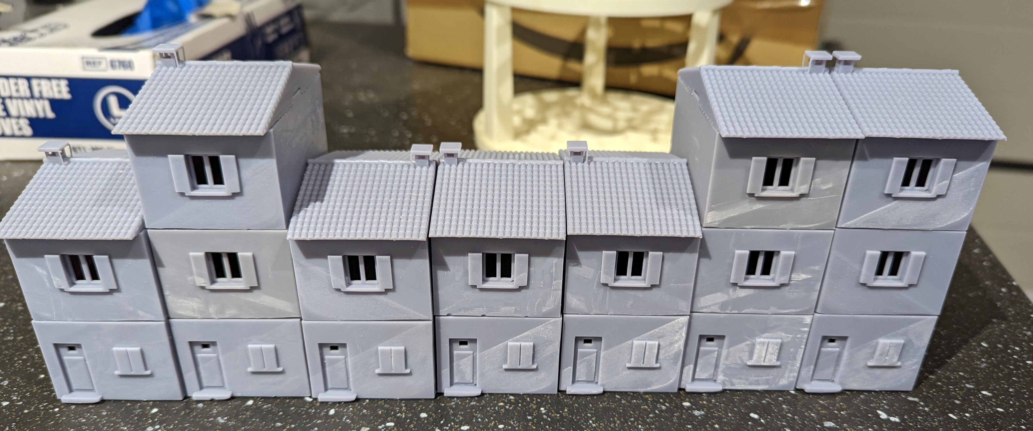
This test was what I have called the ‘small house’ and has a footprint of 4cm by 6cm per level. The two storey house and roof cost £12 plus p&p. I need 7 of these for my village, plus a number of ‘large houses’, shops, town hall and not to mention a church. Cost wise, this is going to add up.
To address this, I dropped some ‘subtle’ hints as to what I would like for Christmas. On the big day, this turned up.
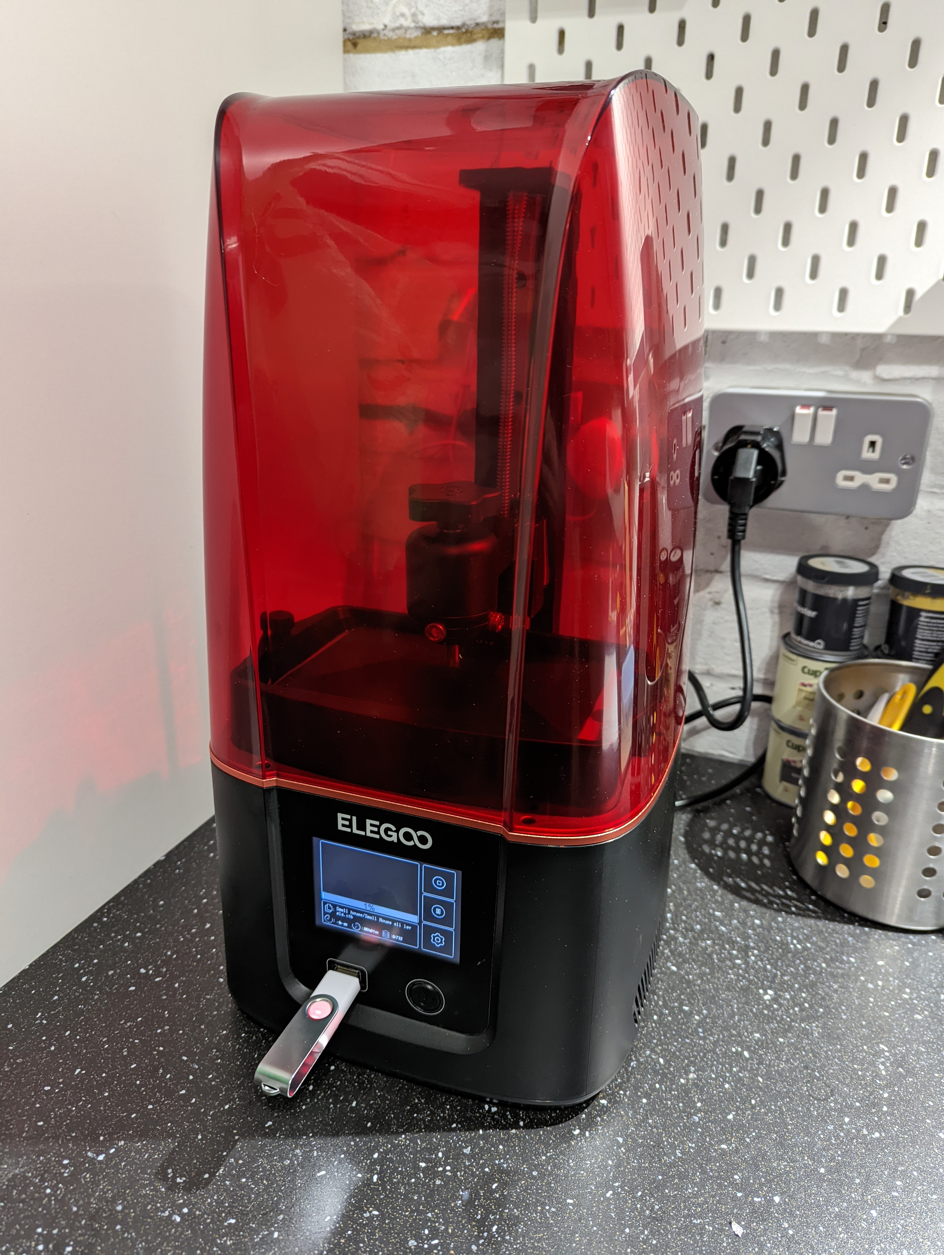
So while the hobby fairies won’t be happy, this is the easiest way forward for getting my prints out. Who knows, they may even end up on MyMiniFactory!
The printer has been busy since arriving and I have been able to print out all 7 of the small houses that I need. There’s been some odd resin lines on some but overall, not bad for a first attempt at designing and printing. I’m sure once they are primed and painted, it won’t show up.
I can now push on with printing out the rest of the buildings!
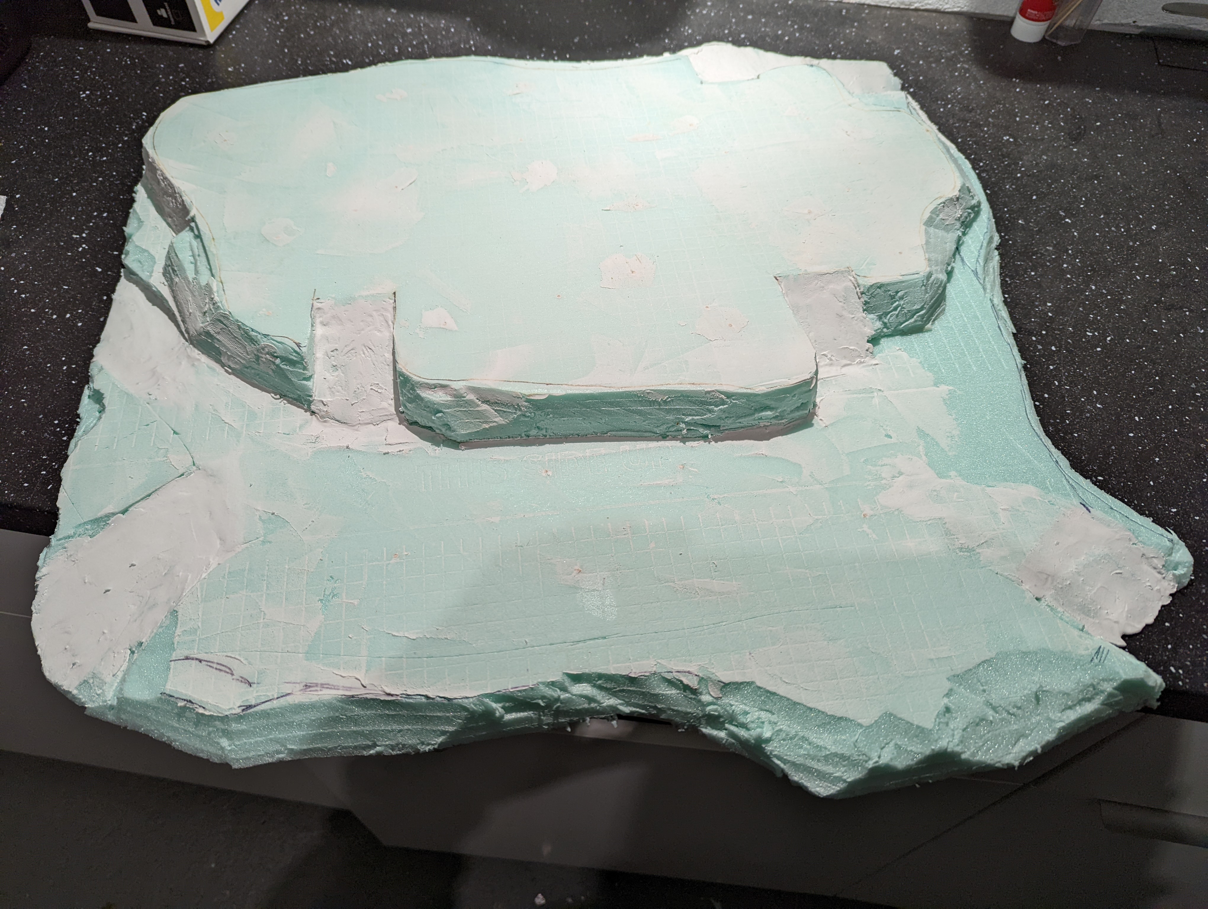
Continuing to piece together the sub-structure
I want the hill village to have two levels to try to create the image of the village being perched atop the hill. In the last update, I created the top level using the plan that I drew up some time ago.
Using the same method of gluing the foam sheets together, I created a much larger area for the lower part of the village. Once dry, I glued the top layer (from the last update) to the bottom layer. This was done using PVA and cocktail sticks to lock everything in to place.
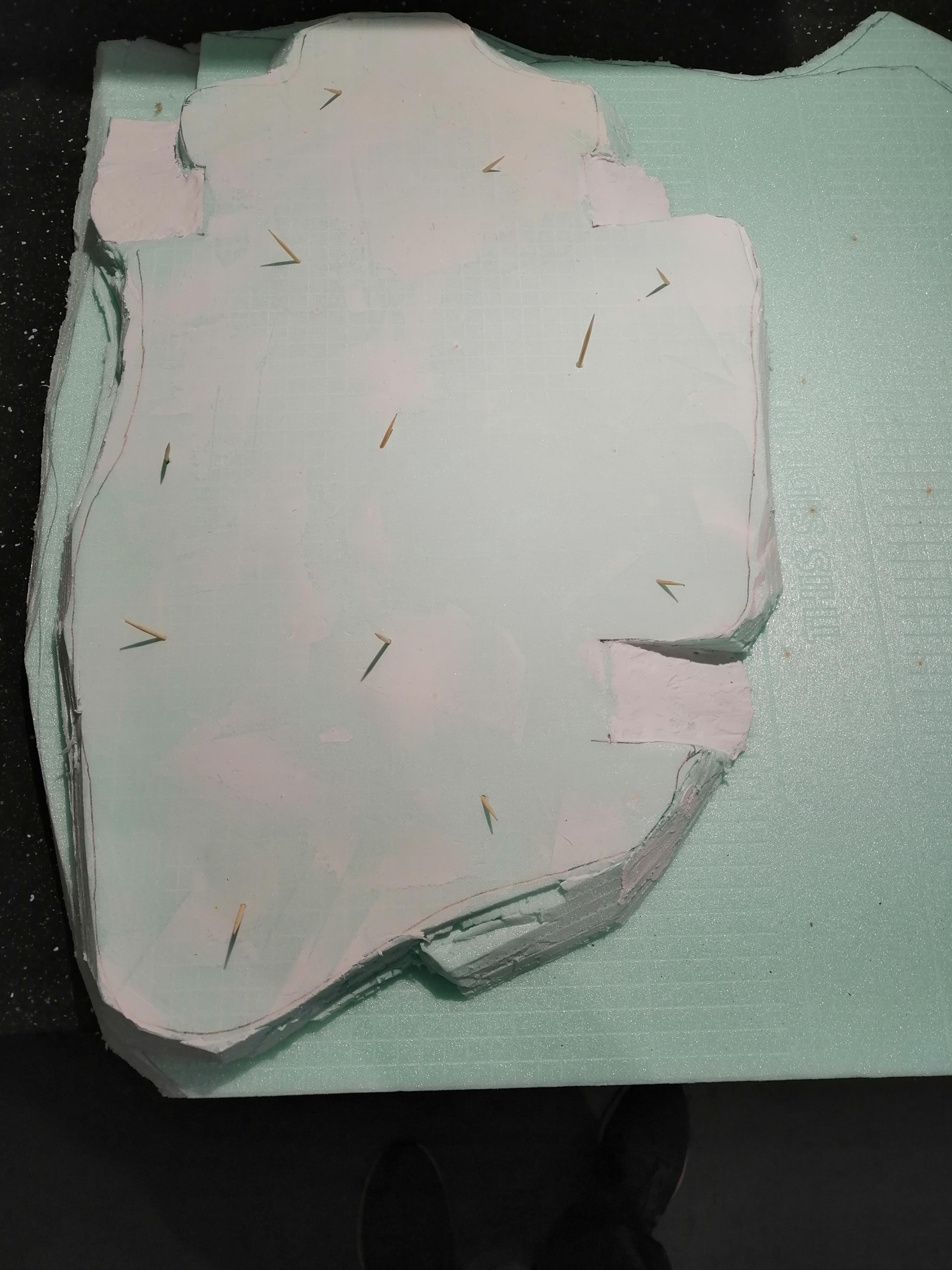 Top layer being attached to the larger, lower layer
Once the glue had dried (it takes several days with this foam), I got to work tracing out the lower level from the plan and began cutting.
 It's all in the planning
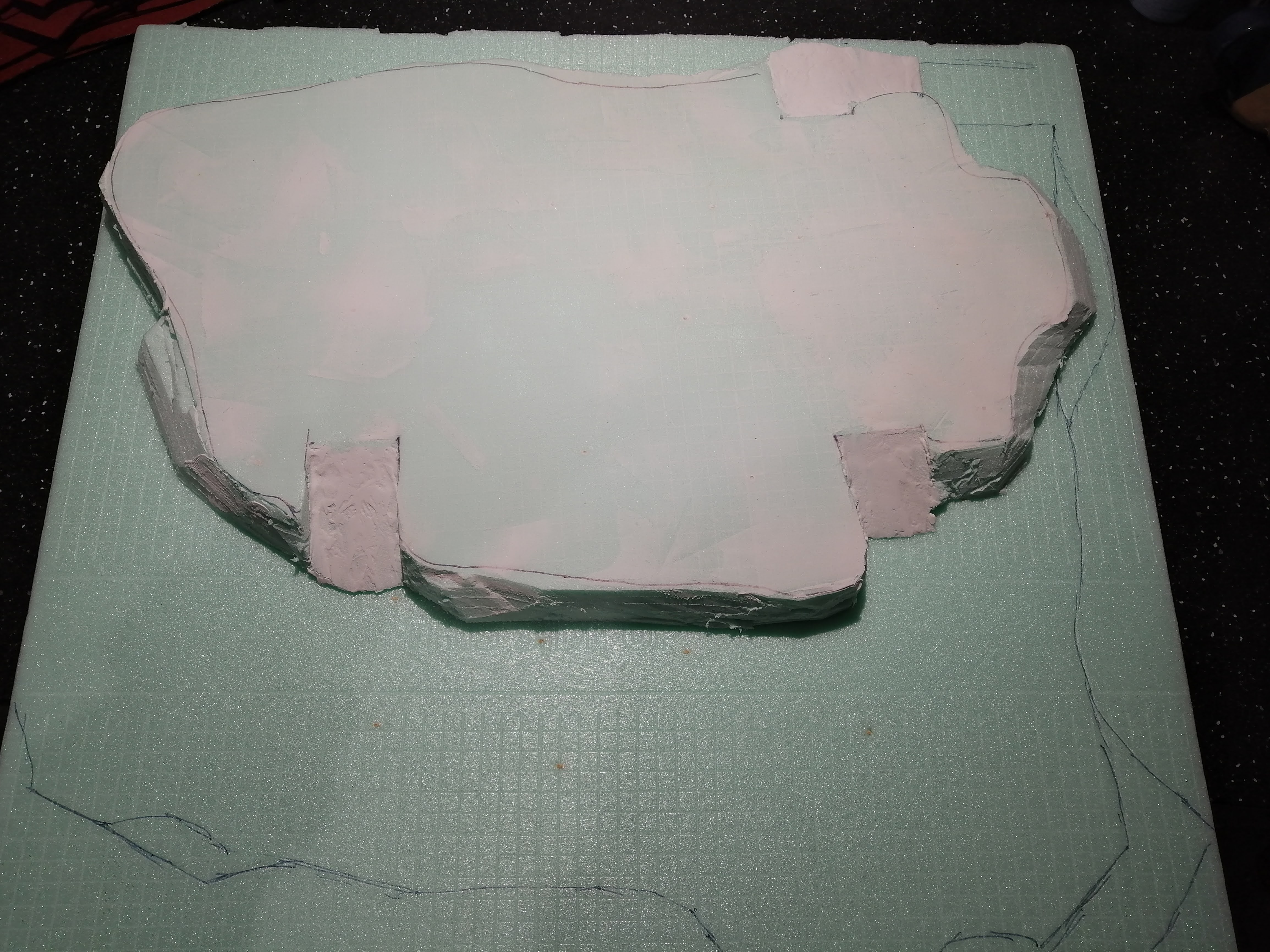
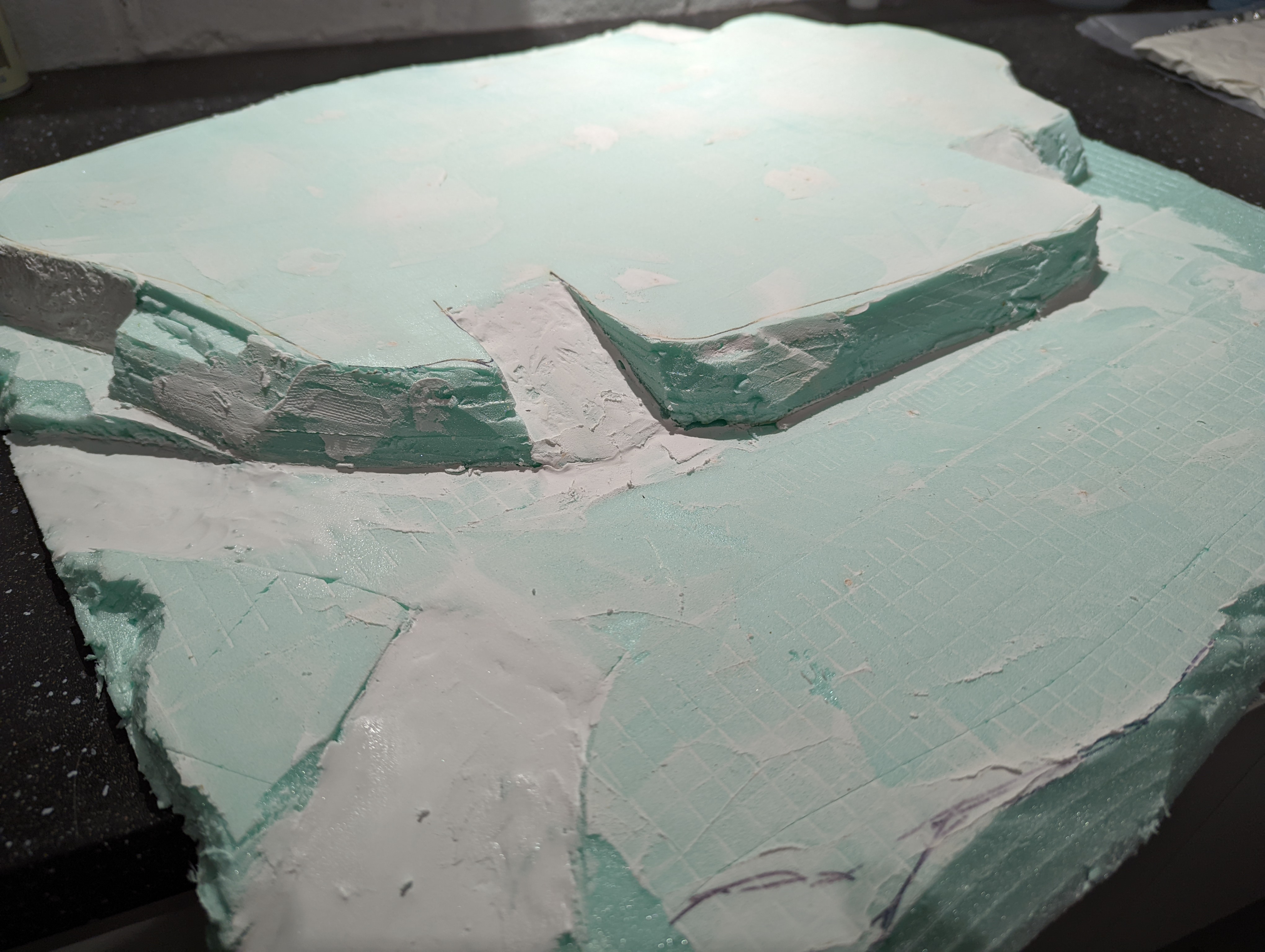
As I don’t have a hot wire foam cutter, I resorted to using a very sharp kitchen knife and applying a lot of patience. For the most part, this worked reasonably well however cutting out what will become the roads up into the village was a real pain in the arse. This took a lot of time and effort to get right, but once I was happy with the cut and the gradient, I applied polyfilla over the top to ensure that it was smooth.
To finish off the substructure, I applied polyfilla around the sides. My thinking here was to use the filla to create a rock appearance by rolling a ball of crushed up tin foil over it. This didn’t really work so I smoothed it out and just used the filla to do what it is supposed to do – fill cracks. I also applied a layer to the top surfaces as this will give me a flat base to work with when I start building the roads.
Here’s how it looks currently
Real World Stuff
Been a while for this project. Probably time to get it moving again.
With the buildings designed in digital format ready for 3d printing (I’m hoping for a printer for Christmas), it’s time to do something in the real world. The buildings will need a hill to be a Tuscany Hill village. So I can get on with making that while waiting for a 3d printer.
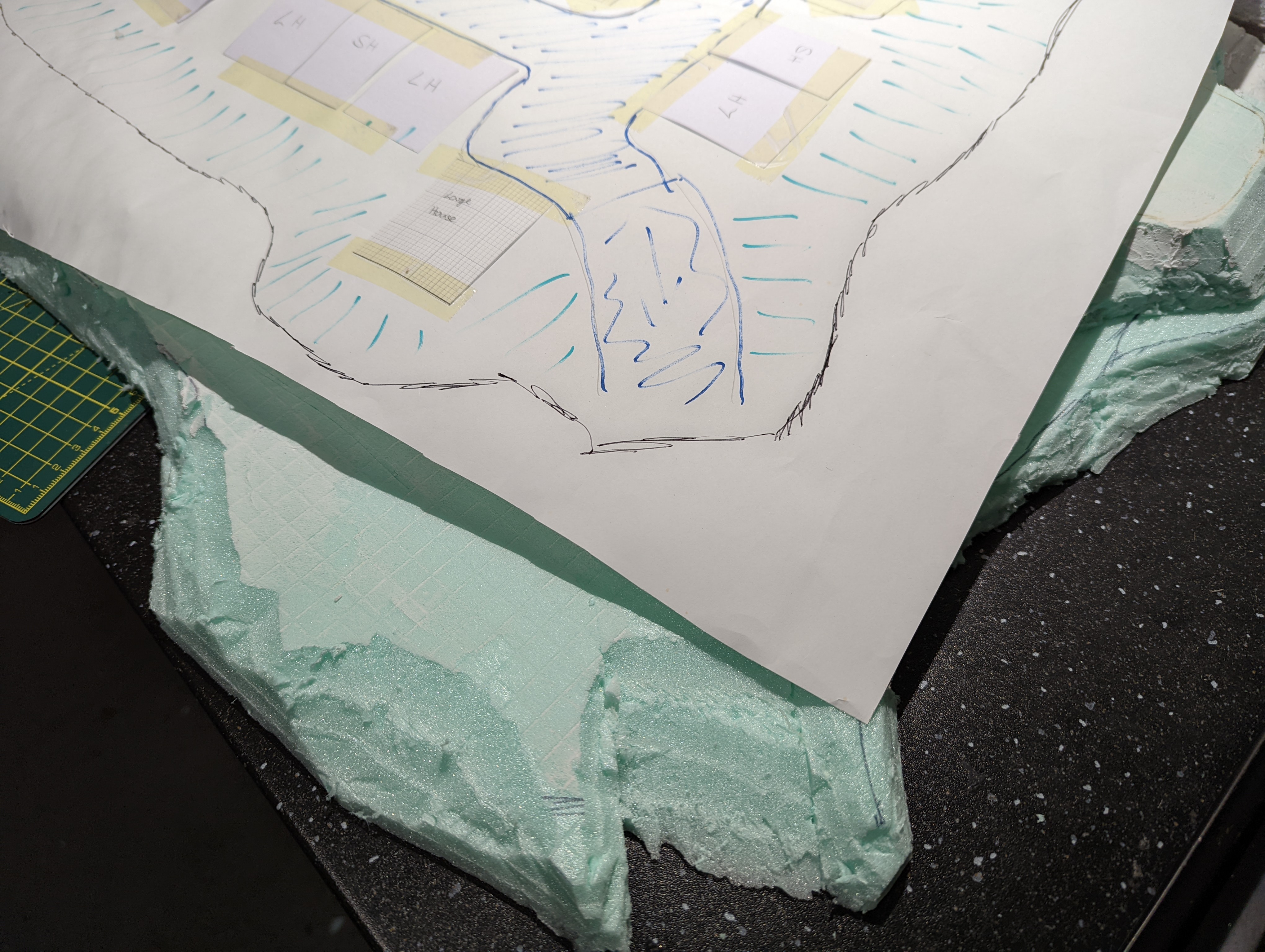
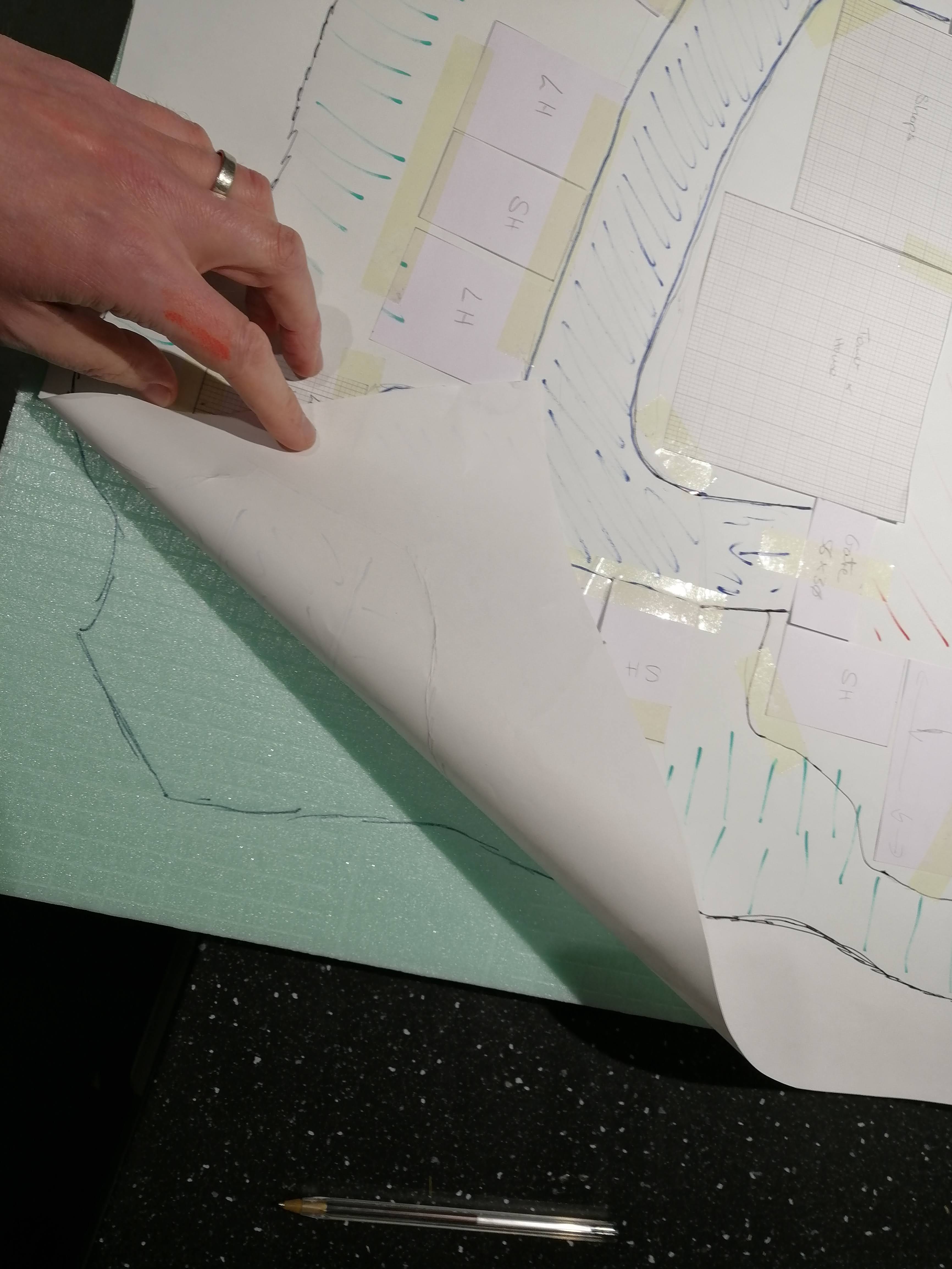
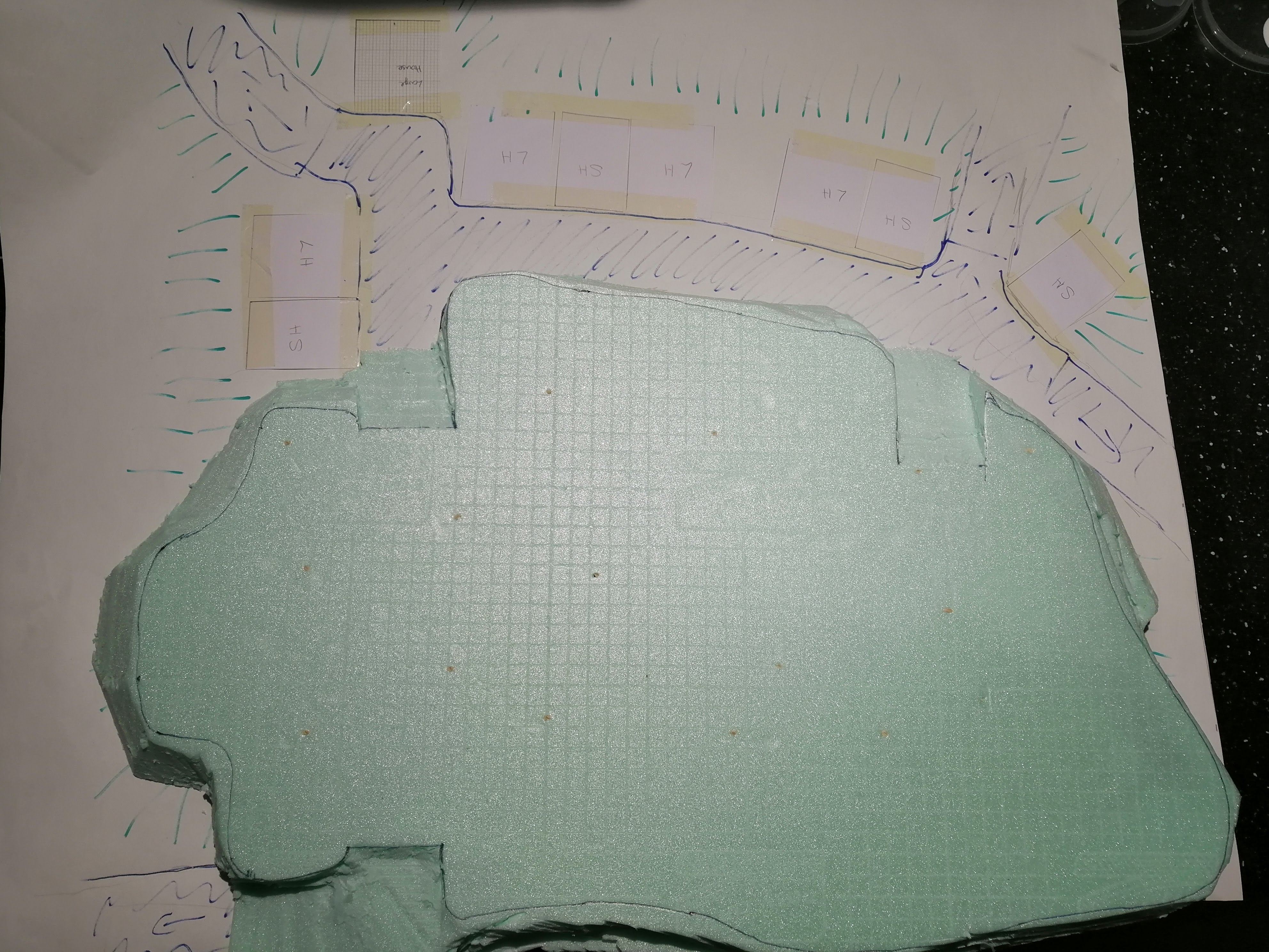
In a previous entry, I had designed the village on paper with a top down view, but for reference, here’s a reminder, expertly annotated with what I’m aiming for.

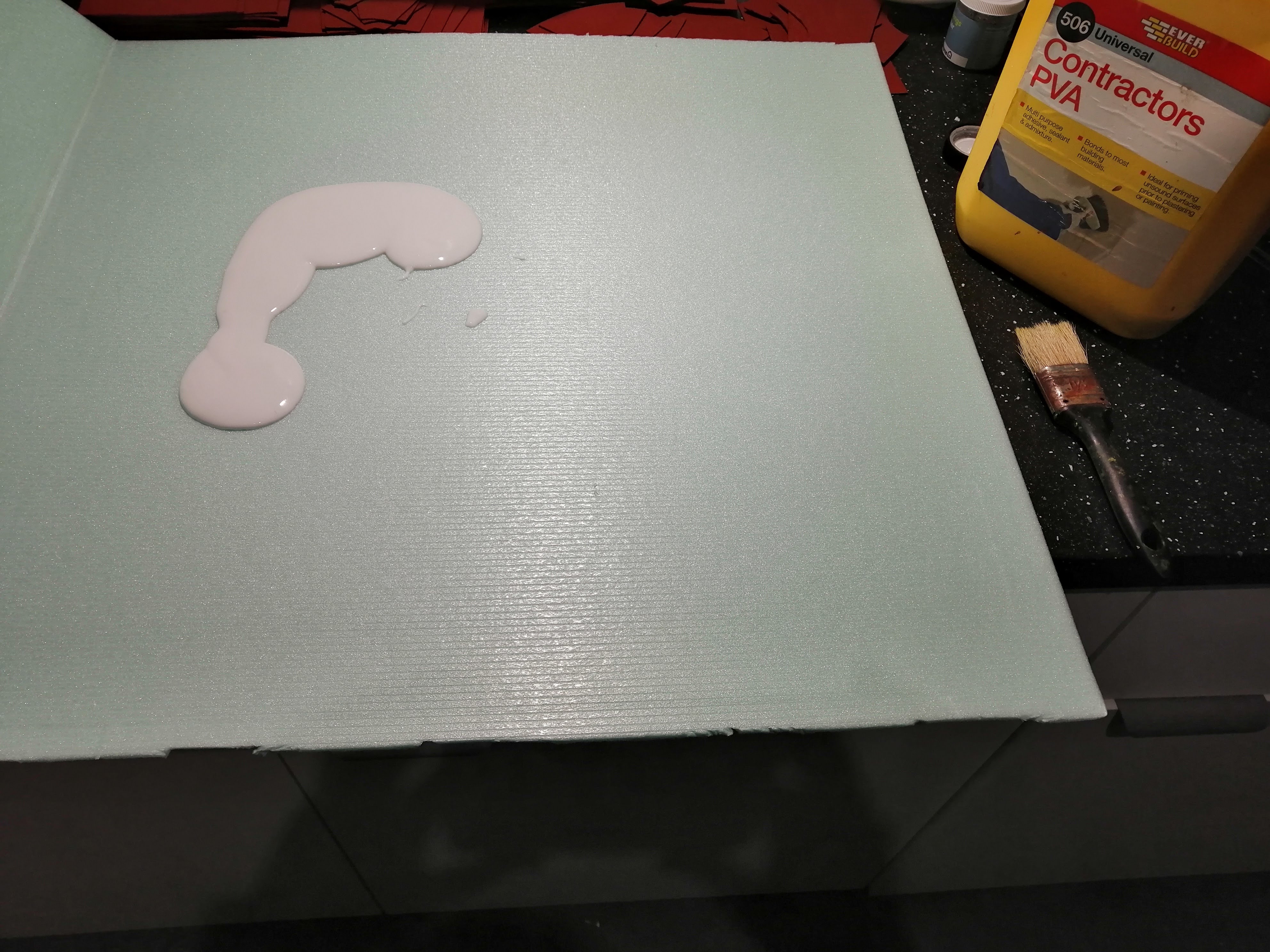
I’m going to make the base out of shower tray insulation foam. This has the benefit of being very cheap and comes in large sheets that are only around 5mm thick. This has the benefit of being able to create ‘layers’ but does require a lot of gluing together. Here’s the stuff:

First step is to glue the layers together using PVA to get the right height. This takes quite a lot of glue. I also use cocktail sticks shoved through at various angles to hold it all in place. This also takes a long time to dry – up to a week!
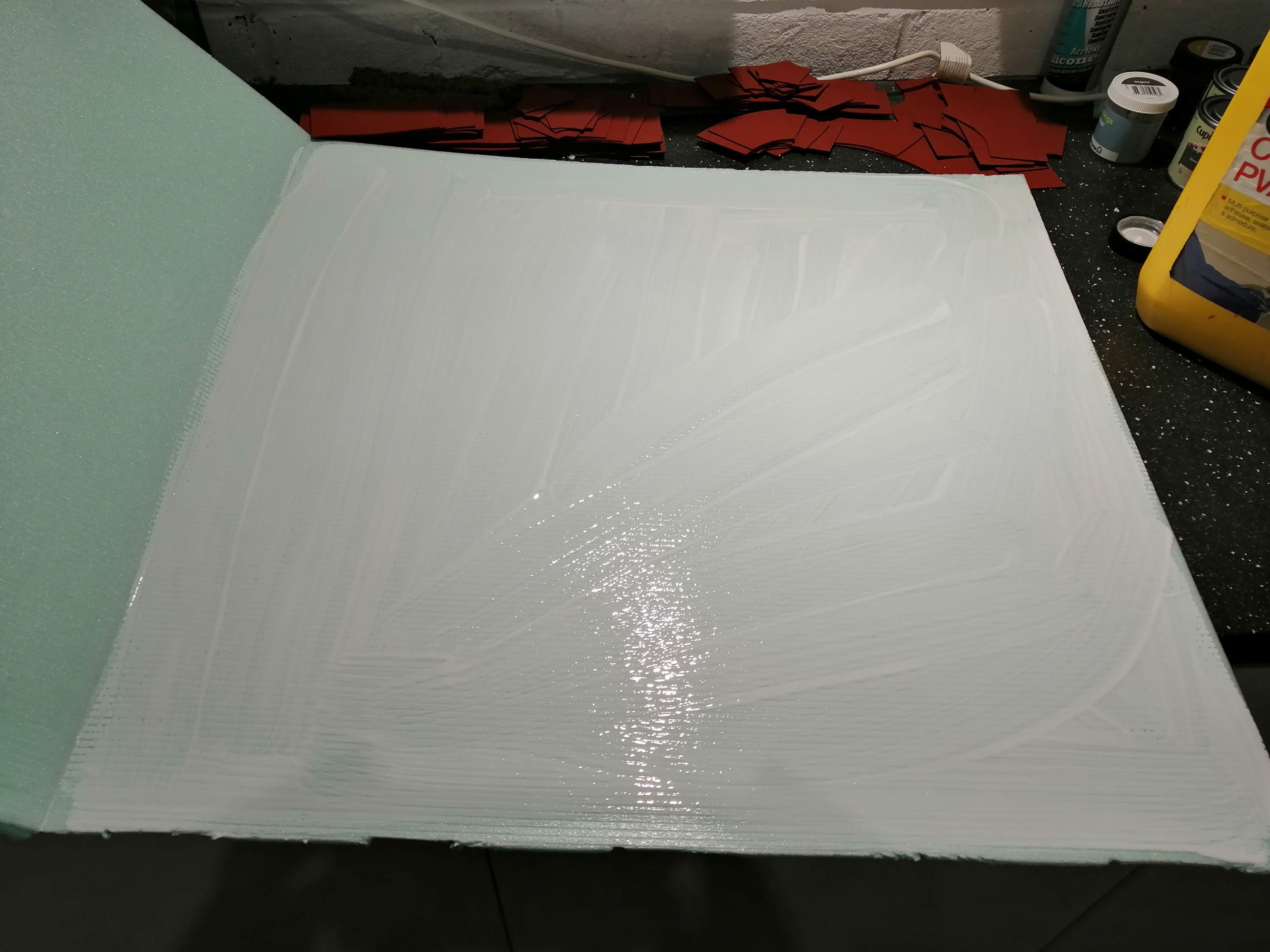

It’s important to trim the cocktail sticks to avoid stabbing yourself with them!
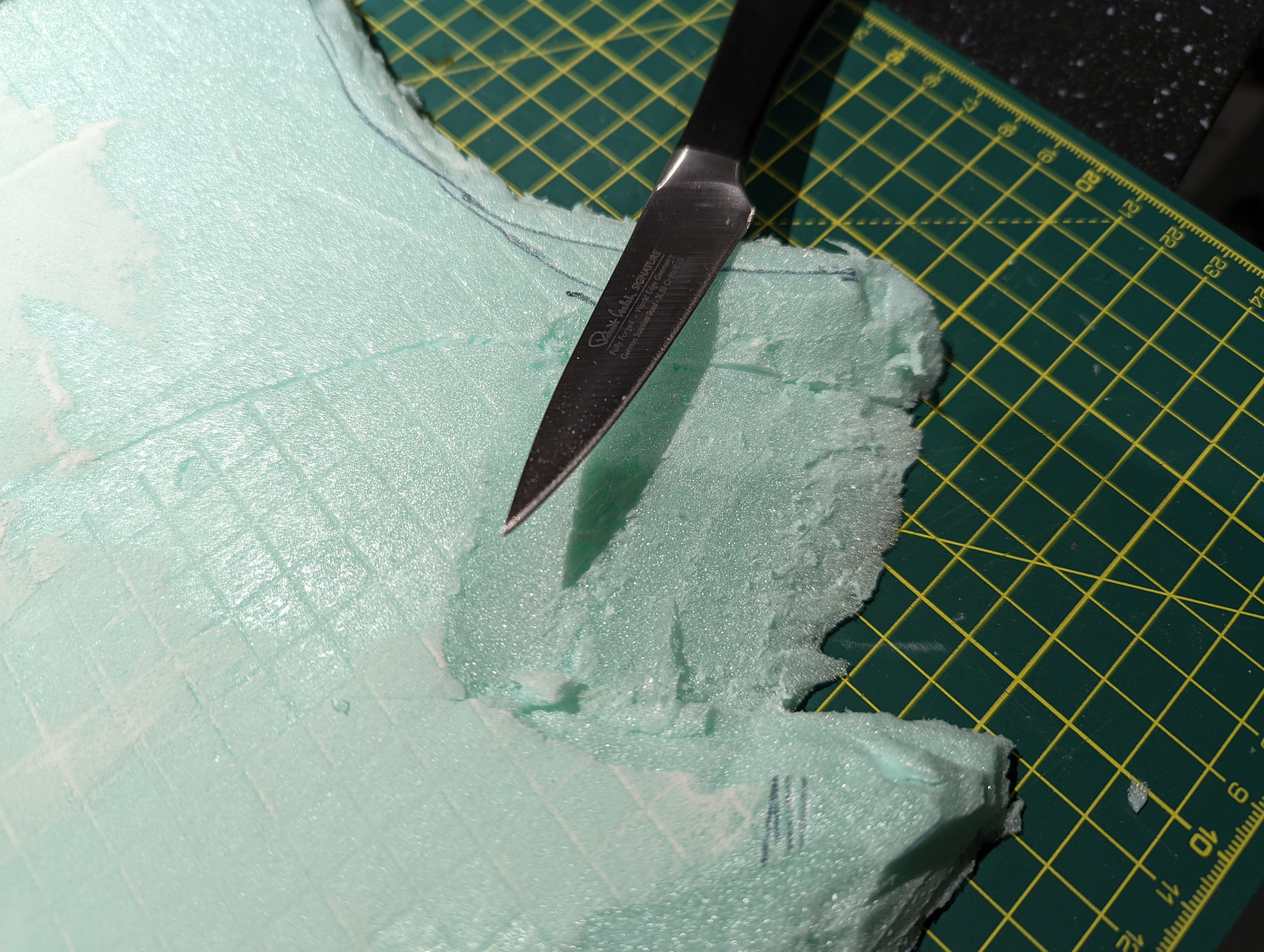
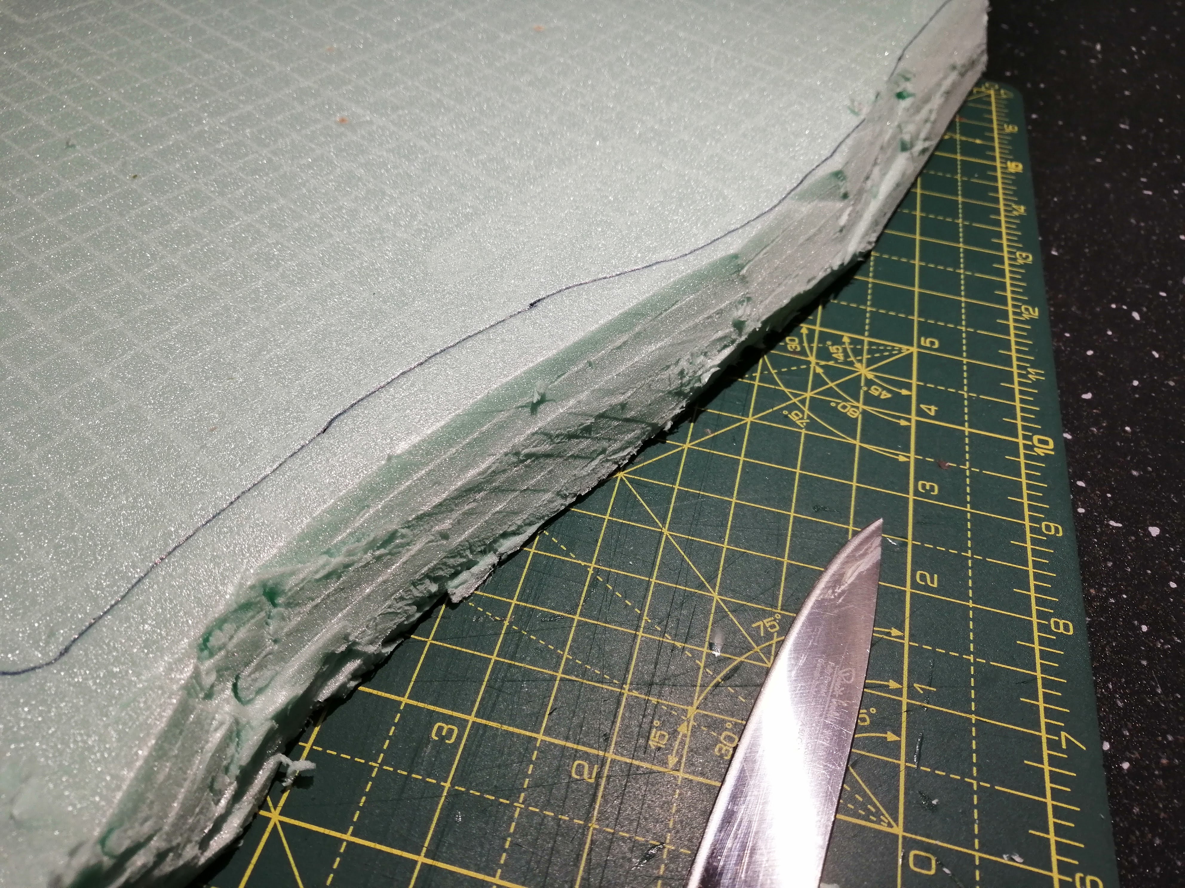
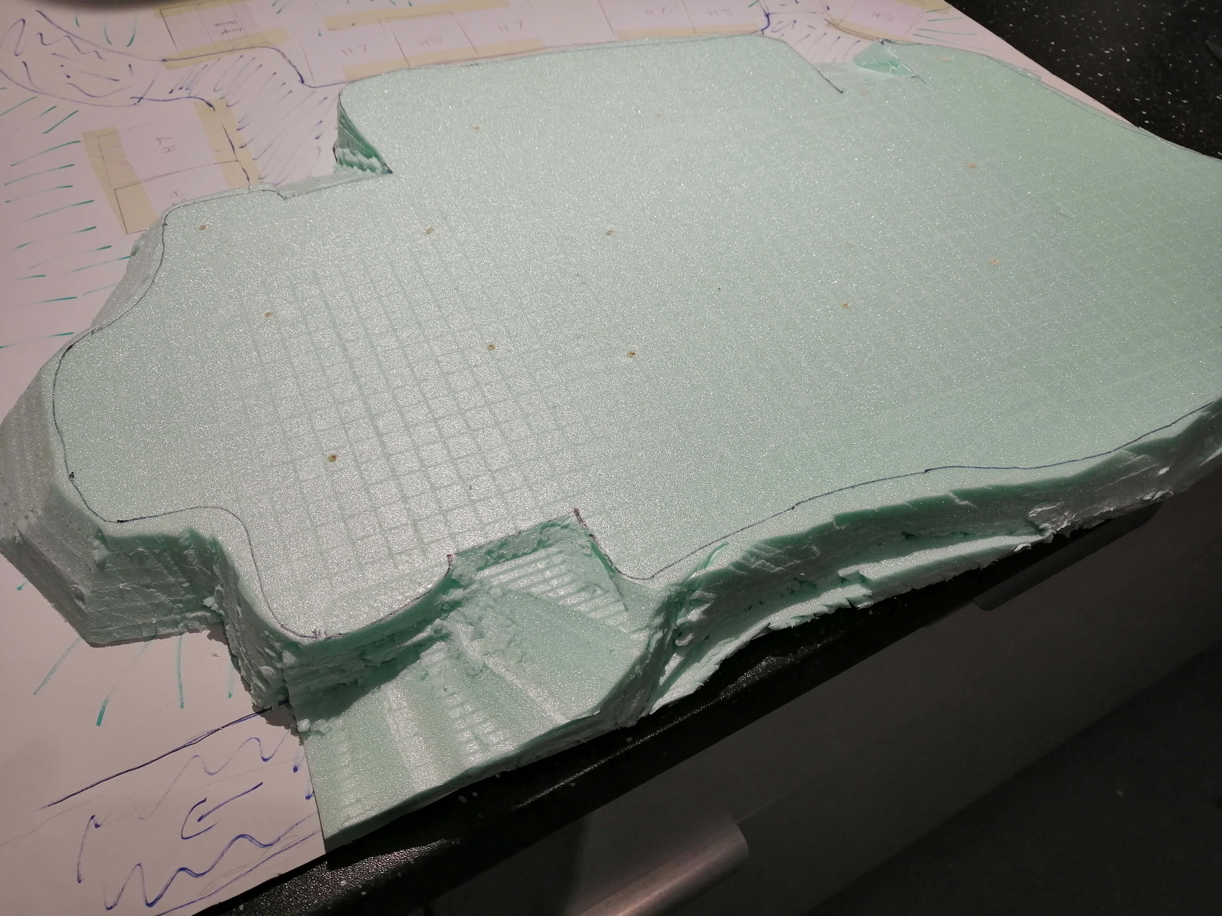
Once everything dried, I was able to begin carving. I don’t have a hot wire cutter but I do have a very sharp kitchen knife, so I used that.
My village has two levels which I will build as two separate foam parts. This is the top layer, which after tracing out the design from the plan, I was able to cut out.
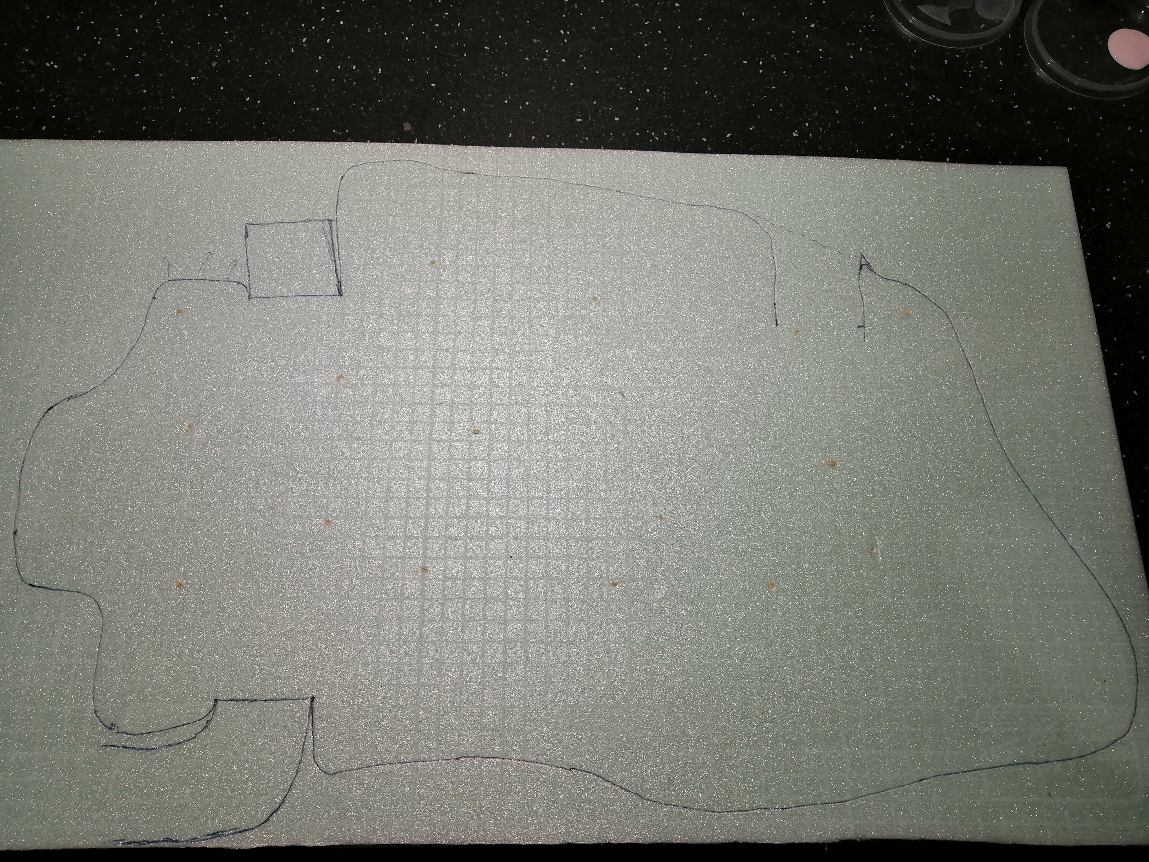
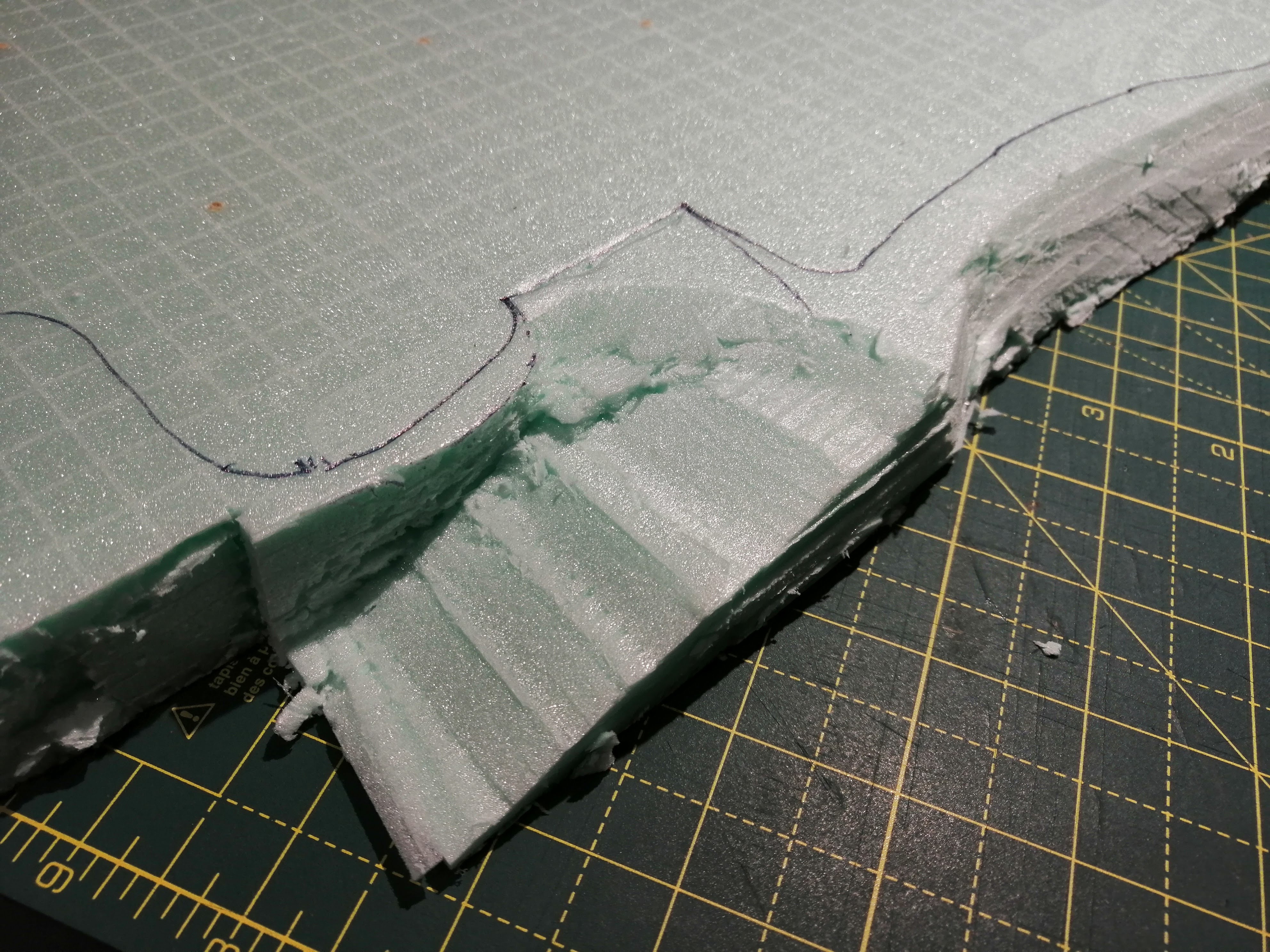
Adding the ramps where the roads up into the village will go was the hardest part, requiring some fine cutting. But as I plan to use some polyfilla over the top to smooth it out before adding the cobblestones, it doesn’t need to be too accurate. Here’s the top layer carved and ready to go.
My Church and how 'Silly Old Hitler Couldn't Advance His Troops Over Asia' came in handy
It’s been a while since my last update. In part because of life and in part because I’ve been working on some Blood Bowl miniatures and some platoons of panzer grenadiers. But I’ve still been tinkering on this project in the background. Why it has taken so long to get to this point is explained below…
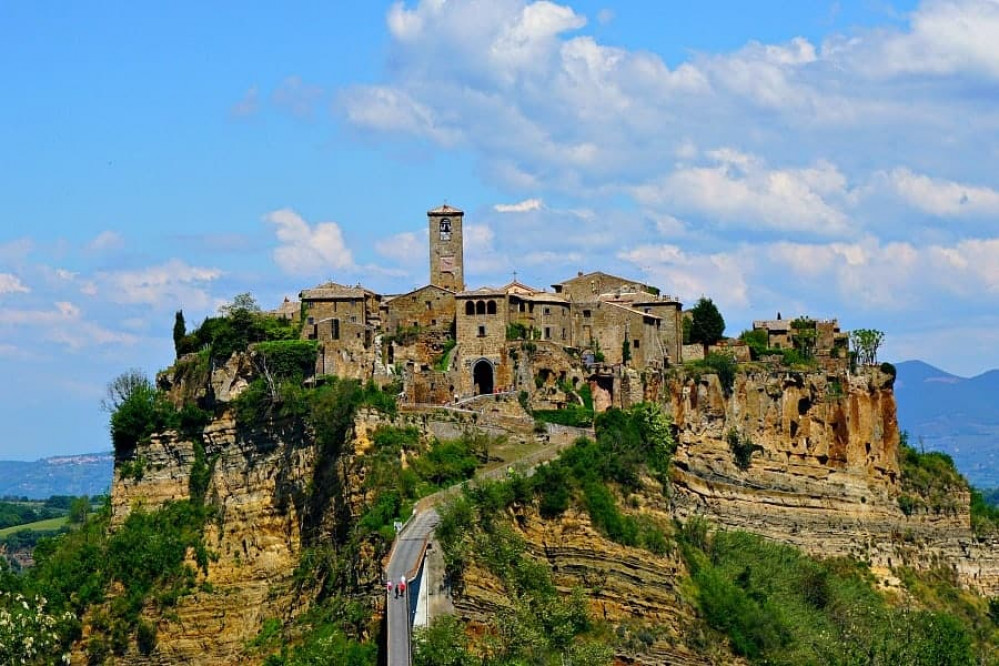
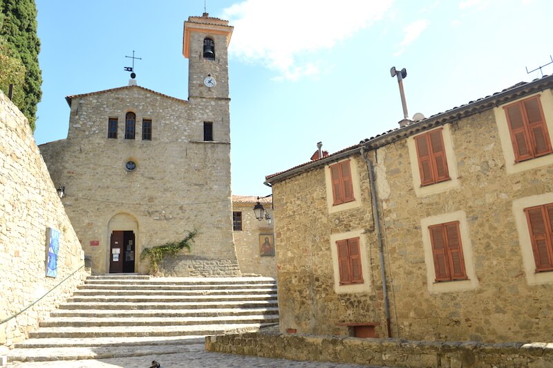
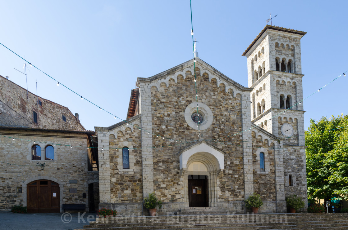
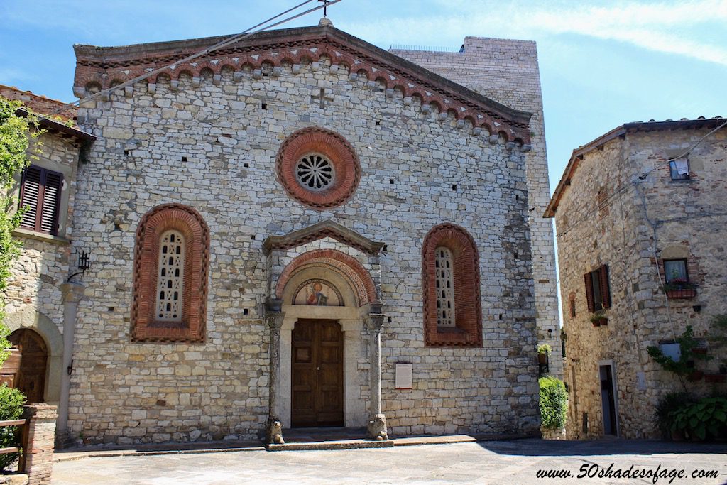
With all of the other buildings for the town now designed, I turned to the most complex, the church. Looking at reference photos, the church is often a main focal point of the town, especially the tower, so I want to try and recreate something that will also draw the eye.
You can see from some of the photos that while there is a distinctive design for the church with the tower being a dominant component.
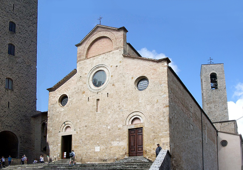
I started on paper, to sketch out my design and to ensure that it would fit into the footprint I had allocated to it in the town plan. My first realisation was that this would be the largest building designed to date, being around 19cm by 10cm. This size made me concerned with regards to the average build space for a resin 3d printer. As I don’t have a printer, I had to do some research into this and my concerns were confirmed – namely that I would struggle to fit this size of building into the build space. I needed to break my design down.
The previous builds have been constructed floor by floor, with my thinking being that the only issue I needed to worry about was how to line up each floor and connect or stack them. Breaking the building into smaller parts that then needed to be fitted together was a completely new challenge.
First issue was ensuring structural integrity and how everything would be put and glued together. I decided that I could tackle the tower like the previous buildings – as separate floors. You can see the tower tiers below, with the lower tiers first, the upper tier and the roof.
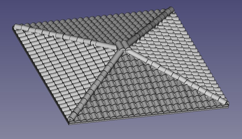
The roof took chuffing ages to design, being a combination of several ‘pyramids’, tricky angles, layered tiles that had to be cut to fit and a lot of pythagoras and trigonometry to get it to work. Just this section took around 3 weeks to figure out! And at least five attempts.

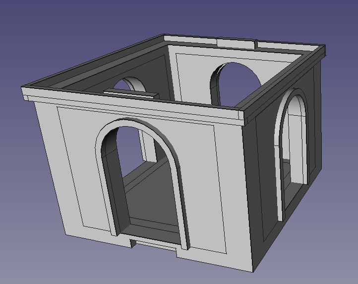
For the main body of the church, I needed a base plate that I could then glue the walls to. The two long walls would be split in two but the end walls could be designed as a single piece, at least up to the height of the roof. The walls would need to be strengthened around the corners to hold them in place so I also designed corner stonework that would then glue over the corner joins. The below image is the base plate with the upright sections designed to align with grooves that will be put into the back of all of the walls.
 The base plate. Not very exciting and won't been seen but nothing stands up without a good foundation
I want the front of the church to be a little grander and so I’ve placed a couple of circular windows into the design. These had to be built separately and then ‘slotted’ into the wall. The same with the door, door arch and steps – all separate pieces that needed to be combined and then ‘slotted in’.
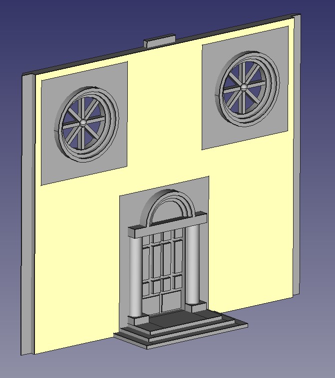 The front of the church
The roof will help define the building and make it look distinctively Italian. I’m going for the double roof look but in making this decision, I’m adding a lot of complexity. The roof cannot be built in one part and so will require internal supports and trusses to ensure that it stays together as well as staying straight and aligned. I also needed to ensure that the roof could lift off to allow access to the inside for the placement of models. Overall, the roof is constructed of 20 separate parts and that trigonometry that I learnt all those years ago came in handy, especially the old mnemonic ‘Silly Old Hilter Couldn’t Advance his Troops Over Asia’!
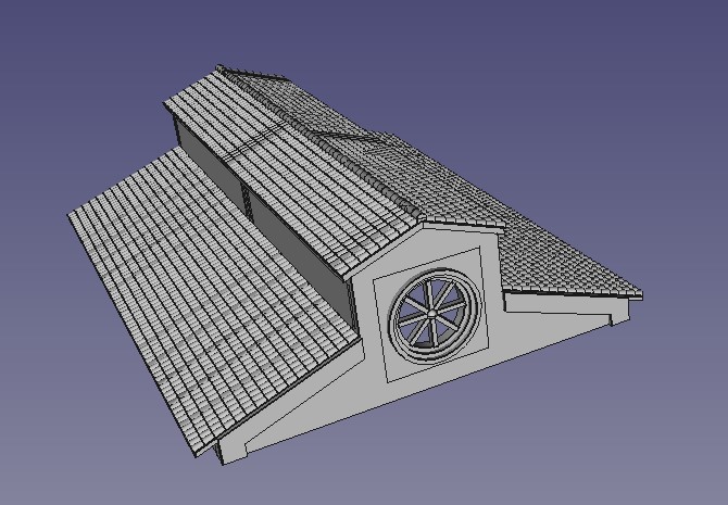 The church roof
So after a lot of effort and redesigns, I have managed to build my church. It all seems to fit together in the virtual world without conflicts or parts not aligning but until it is actually printed out, I won’t know for sure.
I now need to look into getting a 3d printer to prove all of these designs. And while I do that, I can actually start on modelling the ‘hill’ that all of these buildings will sit on – so some actual, real world, physical stuff.
 The completed church from the front
Town Hall
I want a couple of centre piece buildings for the town. One will be the church, the centre of just about every Italian village, but I also plan a town hall. I’ve been looking at reference pictures and particularly like the building below from Cortona.
I’ll take some of the features but try to adapt it to limit its footprint on the table.
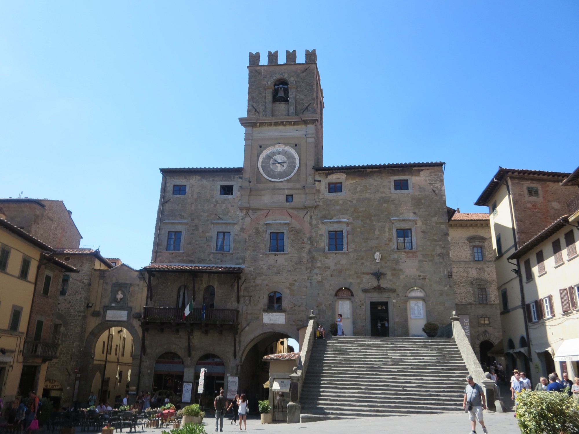 Cortona Town Hall
How I build the Cad designs
I thought I’d add a couple lines on how I design the buildings. Firstly, my cad skills are limited and I’ve had to ‘teach myself’ from YouTube. I’ve found the easiest approach is to break the building down into smaller sections that can be built separately and then combined to make the final 3d print file.
Logically, taking each floor at a time makes the most sense. This requires a basic template and some planning on paper first with the footprint and basic design. To keep the building together once made, I’ve added 1cm long ridges on the top of the two side walls. These fit into the corresponding slots on the floor above’s base and will hopefully be not too noticeable once actually printed out.
For doors and windows, I’ve found ‘punching’ rectangular holes through the walls that are larger than required to be the easiest approach. The door and window can then be designed separately and then slotted in to the hole. You can see below the basic shell of the ground floor for the town hall with holes punched for the windows.
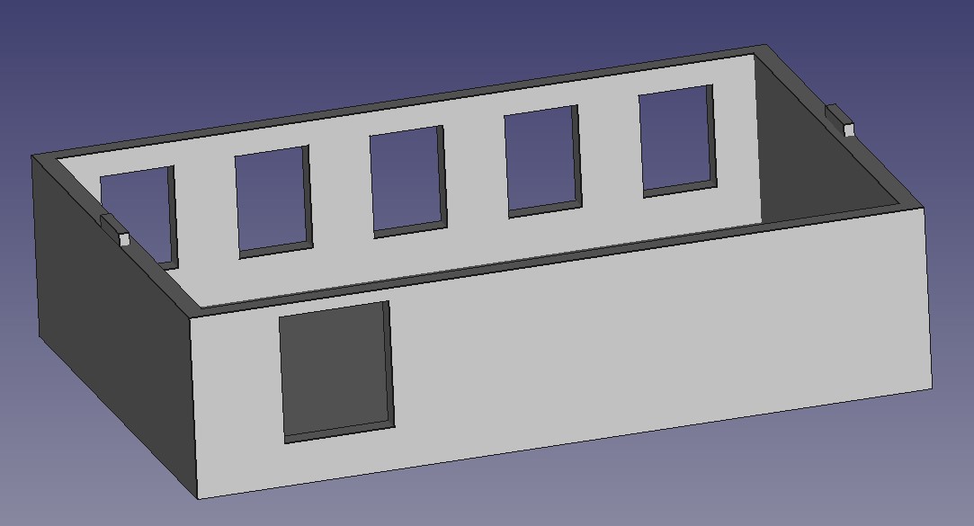 Basic shell for the ground floor of the town hall
By taking the approach to build the more complex parts separately, you can reduce the repetition and break down complex issues into simpler, geometric shapes.
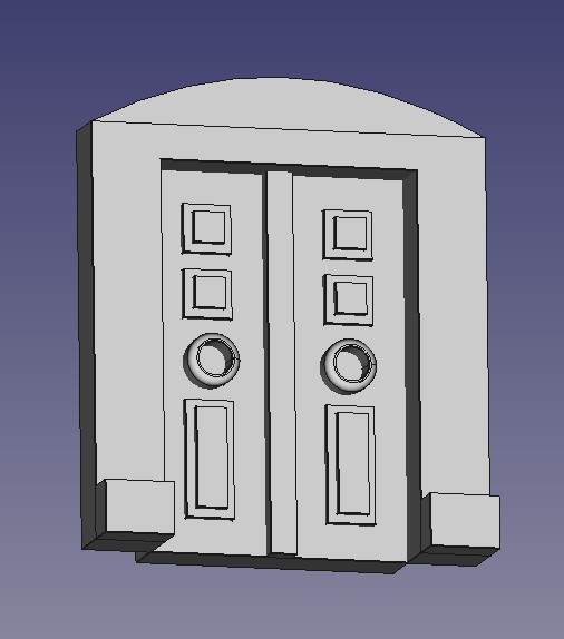
Below are examples of the windows and a door that will get slotted in to one of the holes in the basic shell. The door was in turn built up from smaller parts that were put together. The arch was a rectangle with elements removed. The actual doors had the paneling added before then being slotted in to the arch. This is then combined in FreeCad before being slotted in to the door hole in the main model.

For the ground floor, I wanted to recreate the staircase in the reference picture. However, to reduce the building footprint, I have the stairs running up the side of the building.
The stairs (below) were broken down into separate builds. In fact, the stairs themselves are a series of rectangles placed together. The banisters where the hardest challenge and again had to be created separately and then combined with the stairs to reduce the complexity. The complete stair case was then added to the ground floor shell and the windows added.
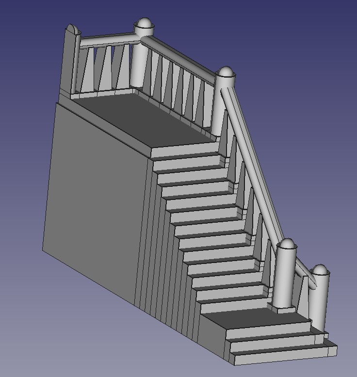 The Town Hall Stairs (from the side that will be attached to the building)
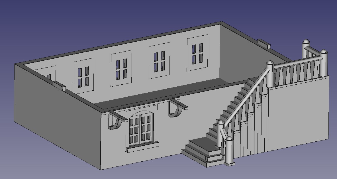 Completed ground floor, with all of the windows and stairs slotted in to place
For the first floor, I wanted the main doorway as well as the balcony. This latter feature took some planning and calculating (I had to go back to my trigonometry lessons from school) to get the angles correct.
The second floor needed a clock face. I’ve opted to actually model the hands into the model rather than paint on once printed. I think this will look a lot better.
The roof took some time to put together. I have ‘sheets’ of roof tiles designed that I import and place on to a triangular sub structure. But that still required a lot of planning to make sure that the sheets didn’t overhang the model to stop issues with the printing when the time comes.
The completed model design is below
 First Floor
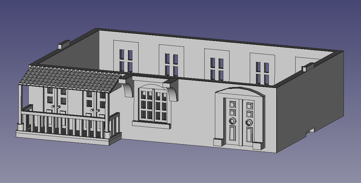
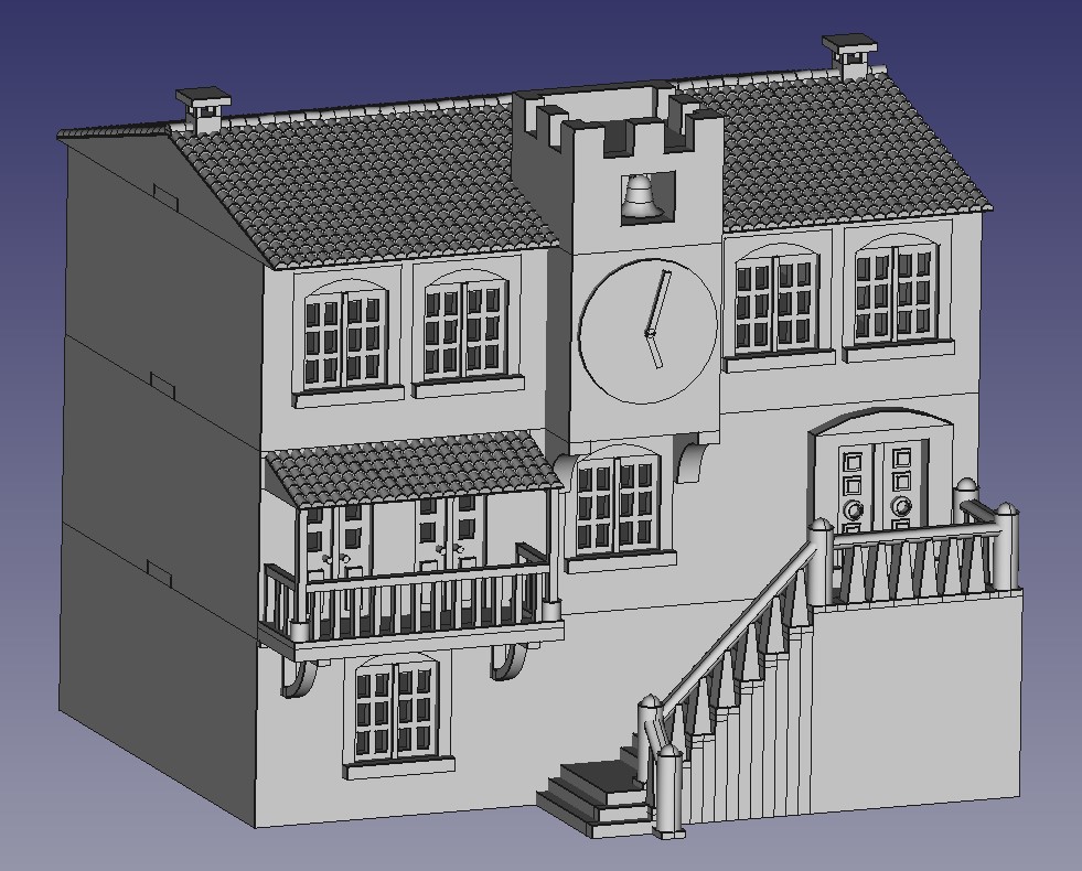 Completed Town Hall