Home › Forums › Technical Support › Changing LED power source from battery to USB powerbank
Tagged: USB LED
This topic contains 13 replies, has 3 voices, and was last updated by ![]() blinky465 3 years, 5 months ago.
blinky465 3 years, 5 months ago.
-
AuthorPosts
-
June 30, 2021 at 10:45 am #1659930
So some of you might remember the LED spots in the background of my videos. I like them. They where cheap, have a remote and make the minis look good.
But they eat batteries like there is no tomorrow and changing them is a nightmare. Each of the six spots needs 3 AA batteries. Now I was thinking of using mains power but on that wall there is no socket anywhere and I don’t want to run a cable across the room. So I though, maybe I could convert them into using a USB powerbank.
Questions for the audience, because my google-fu didn’t bring up any viable solution:
- Are there adapters that fit inside a 3x AA compartment that feed of USB power?
- How would I best connect all spots? Parallel or in series?
- How big (capacity) should the powerbank be?
- Is this all a waste of time and energy and am I better off buying a new set of LED spots with mains/USB power?
Maybe some friendly folk can help out? (Totally not looking at @blinky465 here)
Any help appreciated.
June 30, 2021 at 11:21 am #1659940just strip the ends of the wires that attach to the battery pack, push those into a wall socket and then push another plug in on top to stop them falling out.
I honestly don’t know why people over complicate things 😛
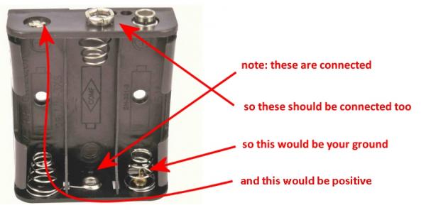
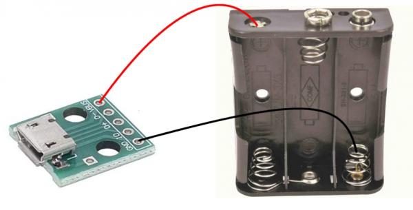
June 30, 2021 at 11:24 am #1659941June 30, 2021 at 5:42 pm #1660038The easiest thing to do would be to buy a few usb socket modules (like this – https://www.amazon.co.uk/YOUMILE-Connector-Adapter-2-54mm-Converter-Microusb/dp/B07TVHR9LF/ref=asc_df_B07TVHR9LF) and either wrap or solder (seriously, solder if you can, but simply wrapping bare wires through the holes if you absolutely must would still work) wires to the outer power and ground pins.
Now wrap or solder the ground wire to the spring of the first battery compartment, and the power/positive wire to the final terminal where the “head” of the last battery would connect.
Since AA batteries are 1.5V (nominal) and three of them in series gives you 4.5V, it’s 99.9% certain that it’ll work fine off a 5V supply. Now you’ve just converted your LED strips to work off any old phone charger.
June 30, 2021 at 5:47 pm #1660044June 30, 2021 at 5:51 pm #1660045June 30, 2021 at 8:50 pm #1660076Thanks @blinky465 but I have 6 of those LED spots… and instead of 6 individual plugs I’d like them to end up in one plug, if possible. Or I’ll need a powerbank with 6 USB ports XD
June 30, 2021 at 9:08 pm #1660077Do you know how powerful your lights are?
Because unless they’re super-bright, arc lamps you could just combine all the power and all the ground cables together and solder them onto the (cut off end) of a Raspberry Pi power supply.
An 11W LED light is super, super bright. And at 5V would pull 11/5 = 2.2A
If your LEDs are 4W or less, you could power them all from a single “official” Raspberry Pi power adapter (or any 5V supply that can provide 3A). Simply divide the power rating of the LED light by 5V to get the current rating.
You could always wire three lights into one and use two power adapters (which would allow you to run two banks of 8W lights). Of course you could just get a single, powerful 5V supply (like you get for LED drivers) that can provide, say, 10A but I was trying to keep it simple, using parts you can easily and readily get hold of 😉
June 30, 2021 at 9:10 pm #1660078Or just twist all your power and ground cables together and use a single 5V/20A LED power supply like this:
That will give you 3.3A per bulb, which means they can each be 15W – and if you’re running six 15W LEDs in a single room, it’d be brighter than the centre of the sun! (the centre of the sun *is* really bright, isn’t it?)
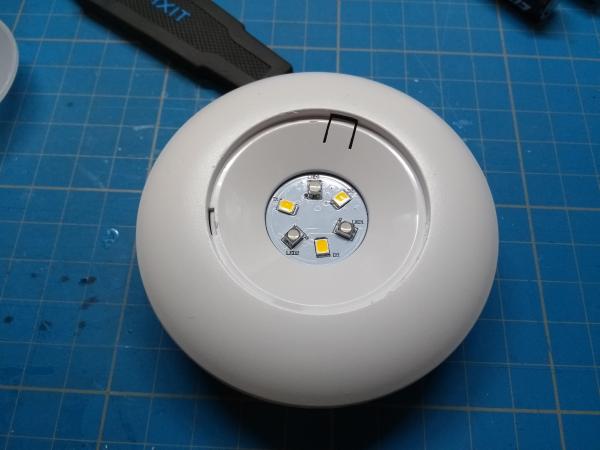
July 1, 2021 at 7:27 am #1660123Since there are no values written anywhere on the spots I did what every responsible watcher of Big Clive does…
I GOT MY SPUDGER AND PRISED THEM OPEN!
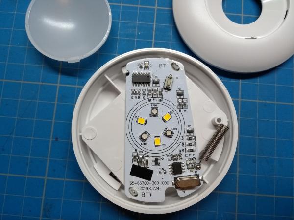
Please see attached pictures to advise further 😉 @blinky465 would you kindly?
 July 1, 2021 at 9:30 am #1660155
Are they controllable? There’s more circuitry in there than I’d have expected for a couple of LEDs! Just a complete shot in the dark, but since your batteries are going to drain from a combined, roughly 4.6V (from fully charged) down to around 3.6V or less as they deplete it’s possible there’s a constant voltage circuit on there (and then instead of applying the full voltage to all LEDs at once, some kind of multiplexing going on). The surface mount push button looks in a funny place – do you press the plastic case of these lights to turn them on/off?
Anyway, all that aside, I’d be tempted to just stick a wire onto each of the BT+ and BT- terminals (it’s a pretty good guess that’s BT for battery and +/- for the positive and negative terminals). If you can, try tracing these to the back where the battery pack is, and double-check that the -ve terminal goes to the “first spring” (see earlier images) and the +ve terminal goes to the “last battery head connector”. I’m almost certain they will.
There’s no way those six LEDs (I’m assuming three white and three “warm white”?) will pull 3A. Those three labelled D1/2/3 may be diodes and you’ve only three LEDs (in which case, current draw will be tiny) but they look all the world like “warm white” LEDs to me?
You might get away with a 10A supply but given the difference in price is only a few pounds/euros, it wouldn’t hurt to use a 20A power supply if you can get hold of one. Simply put wires onto the B+ and B- terminals, wire all the + and all the – together, ram them into the 5V out of your mains-to-5VDC power supply.
Ta-da! No more eating batteries.
July 1, 2021 at 9:44 am #1660179(I’m guessing you don’t have a multimeter or an ammeter you could see what the current draw between BT+ and BT- is?).
Just remembered that these are battery powered – you could *guestimate* the current draw simply by how long they last on batteries? For example, good quality AA batteries have between 1200mAh and 2000mAh capacity (e.g. 1.2A – 2A hour capacity). So if they last, for example, two hours and you know you’re using 2000mAh batteries, you could guess at *very roughly* around 1A current draw (it’d probably be much less than this, since the batteries don’t entirely deplete).
If you’re using cheaper 1200mAh batteries and they last, say, four hours, you’re probably looking at around 300mA current draw (this feels like it’s closer to the actual current draw; a 1A draw off 5V = 5W which is the ~same as a 50W incandecent bulb!).
Personally, I’d allow at least 1A per light so six of them would need a 6A supply just to be sure (this is giving you lots of headroom and room for errror since we’re guessing at a lot of stuff!). A ten-amp supply would probably be good enough and you could still add more lights if you wanted to. But given the cost of a 20A supply compared to a 10A one, I’d probably choose 20 over 10.
July 1, 2021 at 11:19 am #1660219I has a little power measuring thingy (courtesy of Big Clive. It was a giveaway.)
And they are white dimmable and colour shifting. So I guess that’s why 2x 3 LED.
And yes, a small remote for dimming, change colour, turning on and off is there.
July 1, 2021 at 12:26 pm #1660254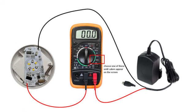
Cut the head off a 5v power supply (phone charger, Raspberry Pi supply etc) and look for the red and black (power and ground) wires if it’s a USB type cable (there should also be a green and a white one in there) or if it’s a twin-wire power-only cable, find the one with the painted stripe on it (this is the positive wire) and connect to the +ve terminal on your multimeter.
The black cable should be labelled COM (it *might* be labelled negative or ground, but here’s one example where this is incorrect labelling!). Connect this to the *positive* terminal on your LED. So the power is basically going from the adapter through the multimeter and into the +ve terminal on your LED light.
Now connect the -ve/ground wire from the adapter to the -ve terminal on the LED. Set to full brightness and switch on.
Depending on which setting you have on your multimeter, and depending on the current draw, you may need to move the dial to get a reading. For example, if your LED is drawing up to 20mA you’ll need it set to 20m (this is unlikely to be the correct setting – a single LED can pull 20mA easily). If it’s drawing up to 200mA (possible, but unlikely depending on how the LEDs are wired) you’ll need it set to 200m on the dial. Anything over 200mA (up to 10A) you’ll need the dial set to 10A for a reading to show up (this is where I’d expect the values to appear).
Don’t forget that at 200m, the reading will be in milliamps (so let’s say it reads 900 on the 200m setting – this is 900 milliamps – not 900 amps!). But depending on your multimeter, you might also get the reading 0.9 on the 10m setting.
Anyway, once you’ve done this, you’ll have actual real current readings (rather than over-estimated theoretical maximum ratings). Simply add up the current rating of each LED and this is the current rating you want for your power supply (it’s possible you might just be able to run all six off a single 3A raspberry pi type power adapter, if they each pull up to 500mA but I equally wouldn’t be surprised if all six LEDs can light at once, they draw an amp or more – it all depends on whether the LEDs are being multiplexed by those onboard microcontrollers).
-
AuthorPosts
You must be logged in to reply to this topic.


![How To Paint Moonstone’s Nanny | Goblin King Games [7 Days Early Access]](https://images.beastsofwar.com/2024/12/3CU-Gobin-King-Games-Moonstone-Shades-Nanny-coverimage-225-127.jpg)


