


![NO Weekender Or Cult Of Games XLBS This Weekend [Updated]](https://images.beastsofwar.com/2026/03/No_Weekender_and_XLBS_this_Weekend-225-127.jpg)


Titan Forge Cyberpunk March Diorama


Recommendations: 208
About the Project
Every month, Titan Forge run a "Plastic Junkies" competition, to win a 3d resin printer. They invite patrons to create a diorama using their terrain pieces and choose the best one. Runners up prizes can win bottles of resin (to be able to print yet ever more miniatures!) I entered the February competition and was placed second (the winner created a pretty awesome looking terrain piece and deservedly took the top prize) but didn't really keep a build log. I'm a bit late starting my piece (it's already mid-way through March) but thought I'd document my build....
Related Company: Titan Forge Games
Related Genre: Cyberpunk
This Project is Completed
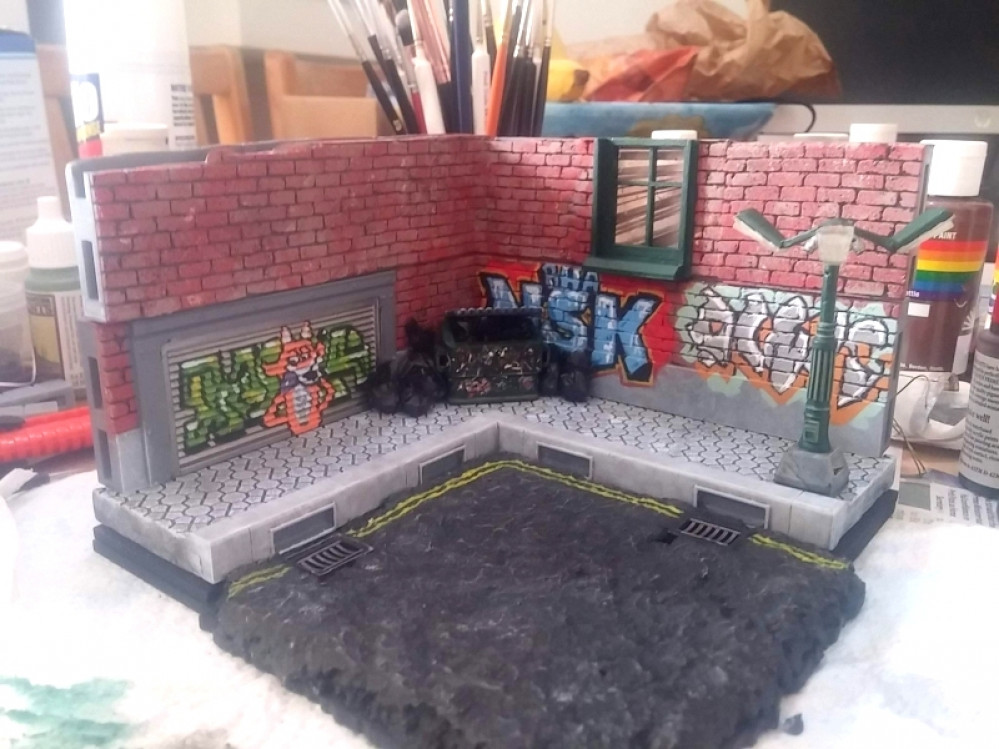
Setting the scene
The example image for this month’s Titan Forge release on Patreon looks really interesting, though I’ve never really been a massive fan of the “open lock” style tilesets. They tend to make terrain look a bit “box-y” and too regular (particularly when used for organic shapes, like dungeons and caves). But the square, modular appearance doesn’t necessarily look out of place for near-future gaming, so I thought I’d print some up and see how they looked.
As I was creating a diorama, rather than an entire playing area, I decided to go for a smaller, more “intimate” diorama.
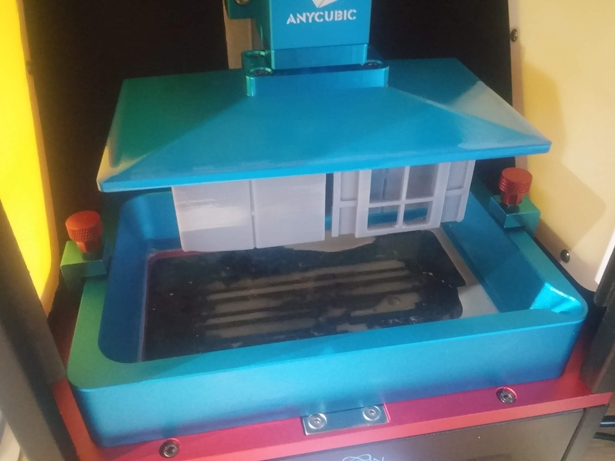
I was printing six open-lock pieces at a time, flat onto the build-plate (I usually angle my prints and use supports, but thought I’d try the flat build, just to see how it worked out).
They turned out really nicely. Except I mis-calculated how much resin was needed on the first print, and ended up with some half-arsed pieces. Still, I reckon with a bit of millput and a file, I might be able to salvage them for use in the diorama.

After a whole day’s printing (I’m not sure that FDM printing would have been much quicker, and certainly the results wouldn’t look as good) I had my first set of open-lock tiles.
On the whole, they came out well. There was a bit of “elephant foot” on the sides that were stuck to the build plate, as can only be expected. I reckon a bit of sanding/filing should get rid of those unsightly ridges.
But in the main, a very promising start!
Adding lighting
One of the models included in this month’s Cyberpunk release from Titan Forge was a three-way street lamp.
I’m hardly likely to give up an opportunity to stick some controllable LEDs in my diorama, so was delighted to see this as my first opportunity to make things sparkle.
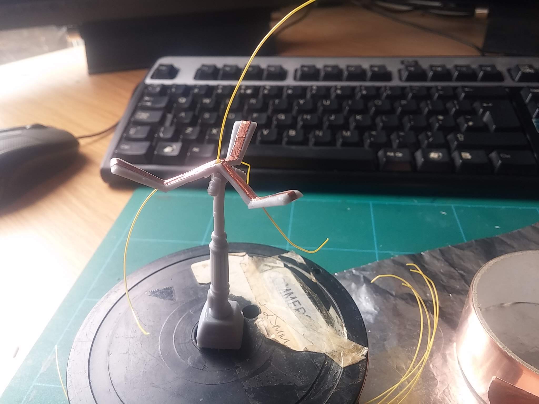
I modified the .stl file in Blender, boolean-subtracting a cylinder from the middle of the lamp-post to create a channel for some fine wire(s) to pass through. I removed the “lenses” from the lamps, as I plan on printing these from transparent resin later.
Then on top of each arm for the lights, I created a channel (again using the boolean-subtract routine) for the wires, and a hole on the “face” of each of the three lights, for the wires to connect to each LED.
A little bit of copper tape on top means I now have a way of creating a common power rail to each of the LEDs. I’m still waiting on the delivery of some amber 1206-sized LEDs, to use as phosphorenscent street lights (I’m sure in the future they’ll have all been changed to LED, but, hey… this is an artistic piece, not a dimensionally accurate architects model!)
Definitely not Back To The Future
One of the models that got a lot of patrons salivating was the ED-209-alike robot (with pilot) in the Cyberpunk range for this March. I must admit, I was temped. It looks great. But I was already half a dozen open-lock tiles into my diorama and couldn’t really see how I could make it fit, without it dominating the entire scene.

I was determined to “tell a story” with my diaroma, so instead, plumped for the car that appeared in the modular terrain folder. After all, I’d already printed a double-width roll-shutter door – what better to go with a garage, than a car to live inside?

Nope. It’s not a DeLorean. It doesn’t matter that they’ve even sculpted the letters DMC into the front bumper. It’s nothing to do with Back To The Future ok?
Actually, I’d already thought about making a Back To The Future scene. I mean, with a souped-up DeLorean model, who wouldn’t? But in the end decided not to. And not just because I could only find slightly cartoon-y low-poly models for Marty McFly (without spending a fortune on CGTrader) – I just felt that I needed to stick to “dystopian cyber future” and not get distracted by “80s blockbuster retro”.
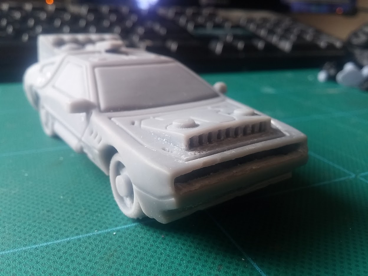
One thing was for certain – whether this *was* the DeLorean from BTTF, or just some random futuristic vehicle, it wasn’t going down onto my tabletop without first being stuffed full of unnecessary technology. Mostly flashing, controllable LEDs.
Originally I’d planned on making the walls of the model at the front and back bumpers super thin and putting 1206-sized LEDs behind them, shining through the cured resin. But after making one of the smallest pcbs I’ve ever made….
…I struggled to fit it behind the wheel arches, to make the LEDs sit behind the headlamps. So I took a Dremel to the front…
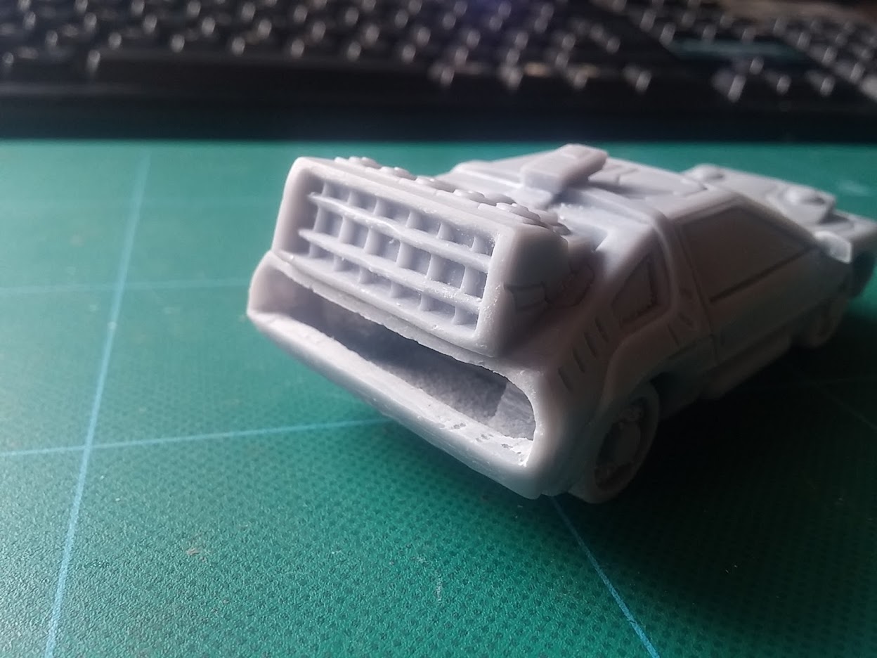
…and rear bumpers of the car, to create a nice big void.
These missing sections will be re-printed with clear resin, so that I can stick the LEDs behind them then pop them back into the car at a later date.
You might want to skip this post if you already have a headache
So, having decided against going down the obvious “Back to the Future” path with a DeLorean in a cyberpunk setting, I had an idea about using it as a getaway car in my little diorama. I put it in a street scene with a couple of n’er-do-well looking types and set about adding LEDs to the headlights, tail lamps etc.
But the entire scene lacked something. There was a “story” there – but “two baddies getting a car out of the garage” wasn’t really screaming *excitement*. What I needed was some kind of tension or conflict.
So I decided to turn the car around, have it pointing “into” the scene, and have some armed police-types aiming at our protagonists. It was no longer a getaway car – but a police car, screeching to a halt at the scene, pinning our anti-heros into a corner in a city street.
Not only would it need light-up headlights, in which to trap the miscreants in its beam, but we’d have to have flashing sirens on the top as well – yet another excuse for even more LEDs. This was starting to look like a win-win.
It meant *lots* of LEDs.
Warning! Super-nerd content ahead.
The car alone was going to be like a christmas-tree with the number of lights on it: two white LEDs for the headlights, of course. Two red LEDs for the tail-lights/brake lights. I figured it’d be fun to add in some indicator LEDs on each corner – another four LEDs.
Then for the siren, we’d need at least two blue LEDs on the top flashing bar. Then, maybe as a nod to our American cousins (or maybe UK police also have them, I’ve never really studied that hard) I thought I’d stick a couple of red lights up there too, so the siren can alternate between red and blue flashing lights.
The obvious thing to do would be to wire all the LEDs and simply turn them on and off. But doing this creates a weird “pulsing” effect, depending on how many LEDs are lit up at any one time – as more LEDs are activated, the total current available is shared between them, so they all appear less bright; if some are turned off and a single LED is then switch on, that one LED appears much brighter with a more intense glow.
This kind of effect looks horrible – especially if the headlights go from dim to bright, for example, as the siren lights flash on and off.
What this called for was a MAX7219….
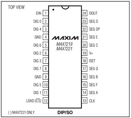
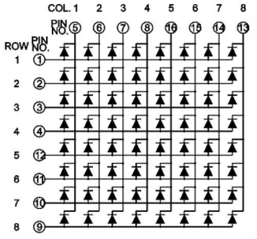
This little chip is a constant current LED driver. It can control up to 64 individual LEDs, and it ensures that every LED gets the same current, so there’s no pulsing of brightness as other lights turn on and off.
It’s usually used as an 8×8 LED matrix driver (and sometimes a 7-segment driver) and it works by lighting up just eight LEDs at a time (one row at a time). But it lights each individual row so quickly (at about 800 times a second) that you don’t see the flicker.
I have wired my LEDs so that they represent individual rows on a matrix (albeit with fewer than 8 “columns” in each “row). So, for example, I’ve put the four LEDs that make up the police siren lights on a single row. The indicator LEDs are on another row. The headlights on another, and the outside street lamps on yet another row.
So when I tell the microcontroller “turn on row zero, column two” what I’m actually saying is “switch on the third LED on the siren lights”. Similarly, when I send “turn off row two, column one” I’m effectively switching off one of the street lights. (counting in microcontroller land begins at zero – so the first “row” is zero, the second “row” is one, etc.)
Here’s a simple test rig, that lights up LEDs using a MAX7219; it cycles through every row, lighting up each individual column.
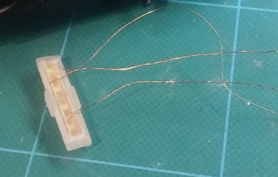
Now I’ve got my LEDs mounted onto a tiny homebrew PCB and I can see that they work with my MAX7219 controller chip, all that remains is to write the sequences to make them flash in the right order to create the appropriate animations…
Not much progress but plenty of prep
The title pretty much says it all. It feels like there wasn’t much progress this evening. But at the same time, a lot was done that means the next time I get the soldering iron out, things will be really cool…
In the meantime, here’s a 32mm scale DeLorean with nice, bright, headlamps (running at 5v).

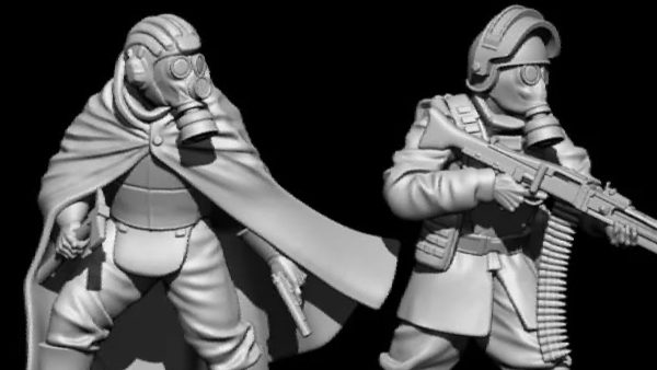
Rattle can zenith highlights
It’s my first time at trying zenith highlighting. And I think I like it.
I tried using my airbrush, but it just spits and splutters all over the place, so thought I’d try using aerosols.
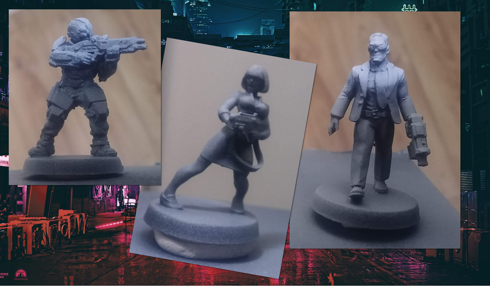
I started by base-coating the entire miniature in Halfords matt black primer. I then hit each one from “just above horizontal” using their grey primer. Lastly, a quick blast from directly above with matt white primer, and the effect was complete.
It’s not so noticable on the soldier-type guy but looks really effective on the suit-guy (and the woman holding the gun). It looks a little bit speckly in places, but I’m hoping that will be reduced once there’s a layer of colour on top…
Things are about to get messy...
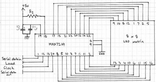
Before creating *any* PCB layout, I like to create a schematic. Although it’s often possible to just squash a few components to gether in layout software and knock up a PCB without one, I find it just helps to organise my thoughts and makes debugging and fault-finding much easier (because, trust me, there’ll be faults to find!)
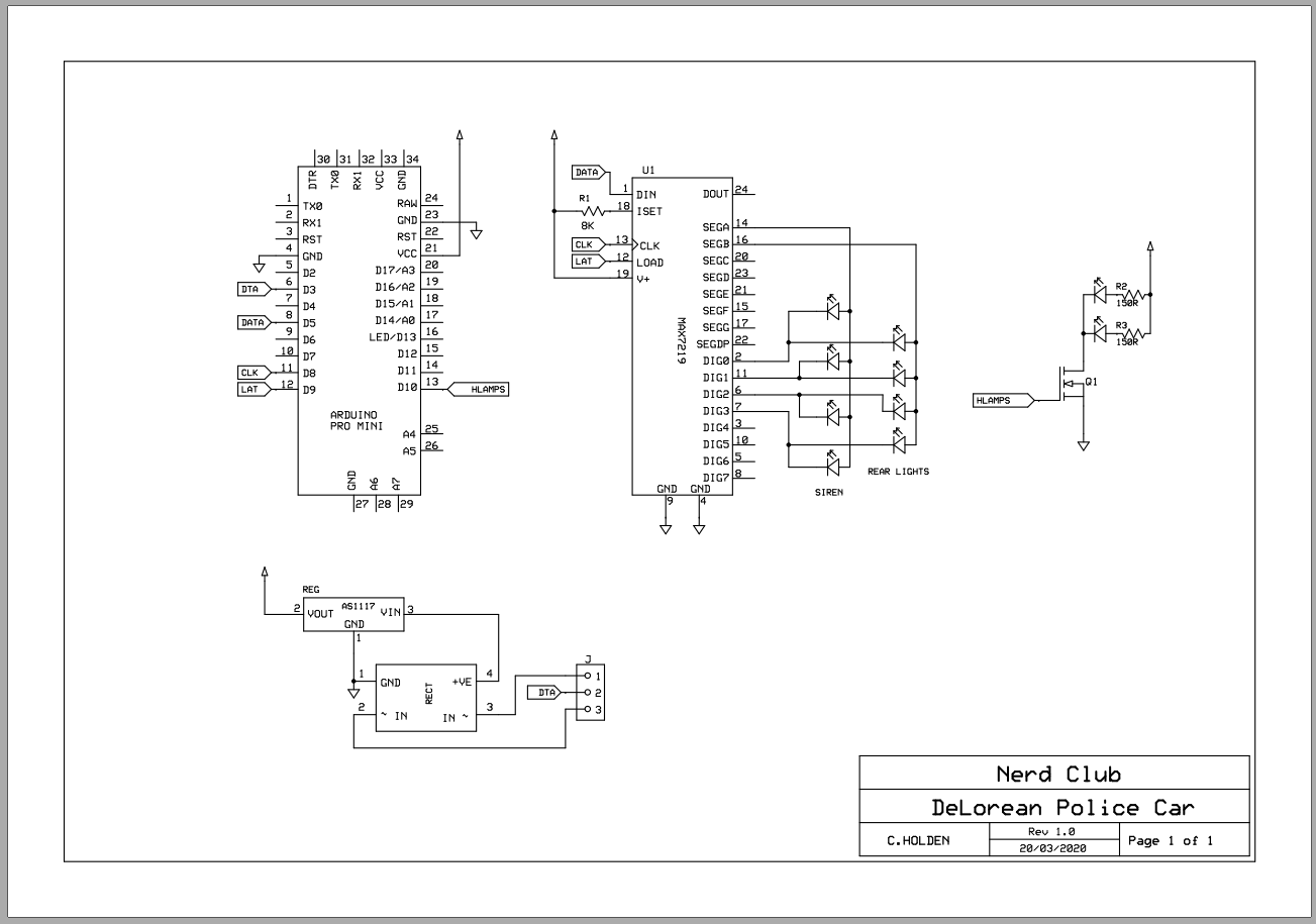
The circuit for my DeLorean police car consists of a microcontroller, a MAX7219 LED driver, a single 2N222A transistor and a bunch of LEDs.
The Max7219 ensures that the LEDs it controls all have the same, uniform brightness. The transistor allows me to connect the headlights directly to the power rail, so that they can shine just a little bit brighter.
See, the Max7219 works by lighting up a single “row” of up to eight LEDs at a time; it does this really, really fast, so there’s no visible flicker. But it *does* mean that every LED spends a proportion of it’s time turned off.
At 800Hz you don’t get flicker, but it does make the LED visibly less bright than if they were connected directly to the power rail. It’s a compromise I can live with for the rear brake lights, indicator lights and police siren. But for the headlights, I wanted them as bright as possible, so connected them separately.
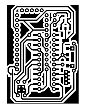
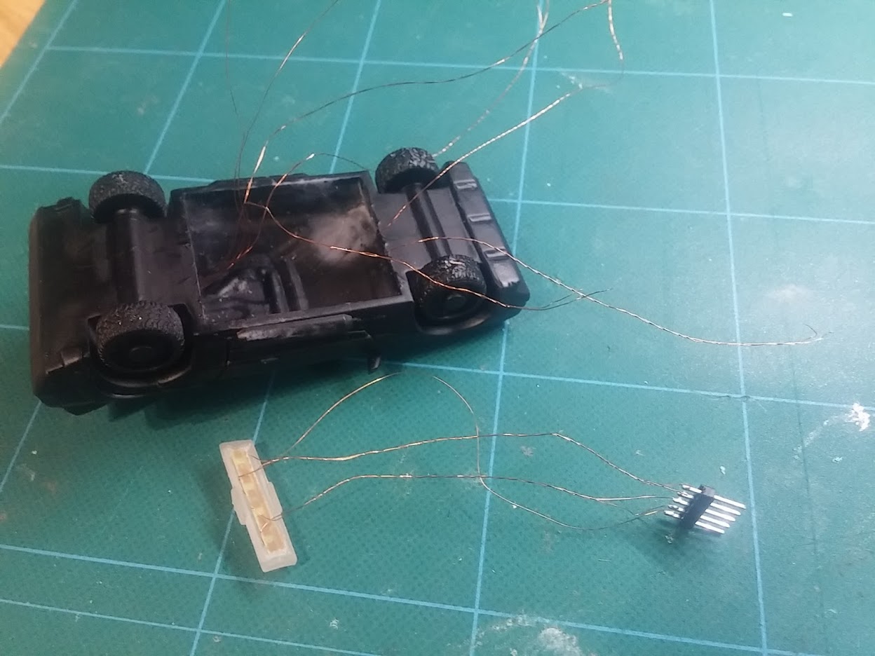
With only a week til deadline day, I figured I’d only got time to make use of the components I had lying around – pre-populated Arduino Pro Mini boards and the larger-format DIP packaged MAX7219 chips. In an ideal world, I’d use a single TQFP AVR Atmega328 chip, a wide SOIC packaged Max7219 and surface mount transistor(s).
As it is, I’m having to use physically larger components. And no matter how hard I tried, no matter how close I squashed the bits together on the PCB, on a single-sided board (without sending the designs away to be turned into a double-sided, factory made circuit board) I couldn’t make it small enough to fit inside the cavity I’d created in the car body.
Which meant only one thing.
It’s the one sentence every electrical engineer shudders at:
“There isn’t time to do this properly….. we’ll have to dead bug it”
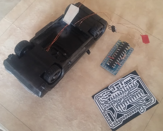
Dead-bugging is the process of wiring components together using wires to connect each of the pins. It’s relatively quick (compared to printing, etching, drilling and populating a PCB) but it’s an absolute nightmare if anything goes wrong, or needs amending in the future.
But time is tight. There isn’t time to do this properly.
So it’s time to get messy…..
App controlled terrain? Oh go on then
Of course having flashing LEDs and blinky lights in tabletop terrain is cool. Although this project is for a diorama, I’m trying to build it in such a way that each component part can be re-used for actual tabletop gameplay. Which means making things “pluggable” and modular.
With that in mind, here’s the first step in an app-controlled diorama (that can then be used as individual app-controlled terrain pieces).
Yes, it’s the DeLorean from Back To The Future.
But in my cyber-world, it’s the standard model for all law enforcement agencies. That’s why it’s got a police siren on the roof! I figured that BTTF was just a bit too “obvious” so tried to make something a little more interesting.
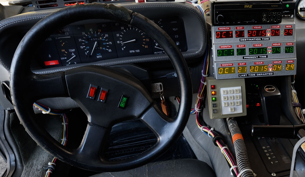
That said, there’s absolutely no reason why I shouldn’t use the first image from a Google search for “DeLorean car interior” for my controller app!
(for anyone interested, the app was written in Unity 2019 using a bought bluetooth library from the Asset Store so it can be compiled to work on both Android and iOS phones and tablets)