


Digital dice roller


Recommendations: 392
About the Project
This is the 21st century, not the Stone Age! Still rolling little shaped bits of bone to generate a bit of randomness in your gaming? Get with the future guys!
Related Genre: Game Aid
Related Contest: Spring Clean Hobby Challenge (Old)
This Project is Active
Creating an enclosure
The first thing to do is to measure up our components to work out how large a void we need to encapsulate our all electronic gubbins. From here we can work out how small we can make the enclosures.
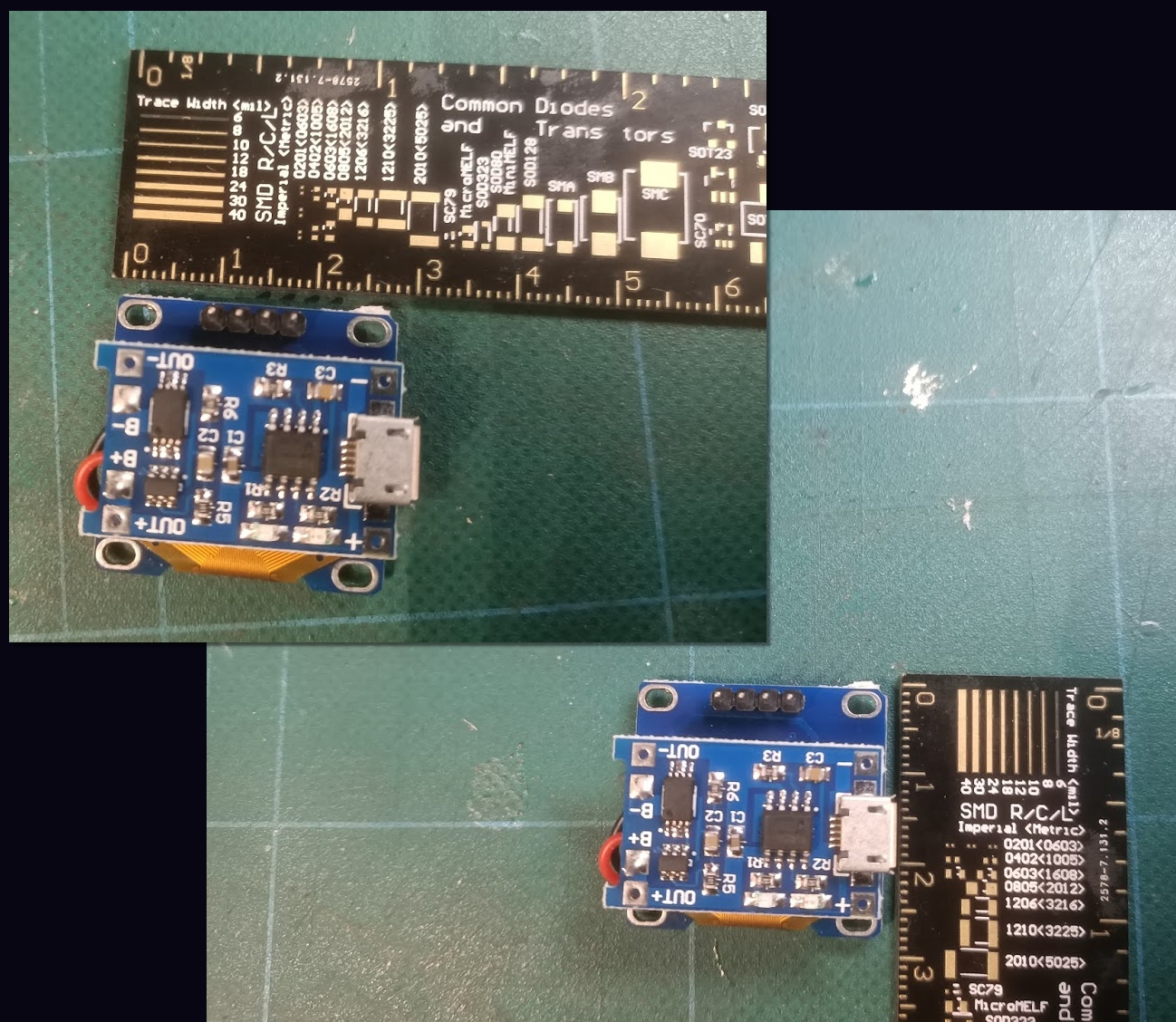 This involved little more than simply measuring, with a ruler, how much space the components were likely to take up.
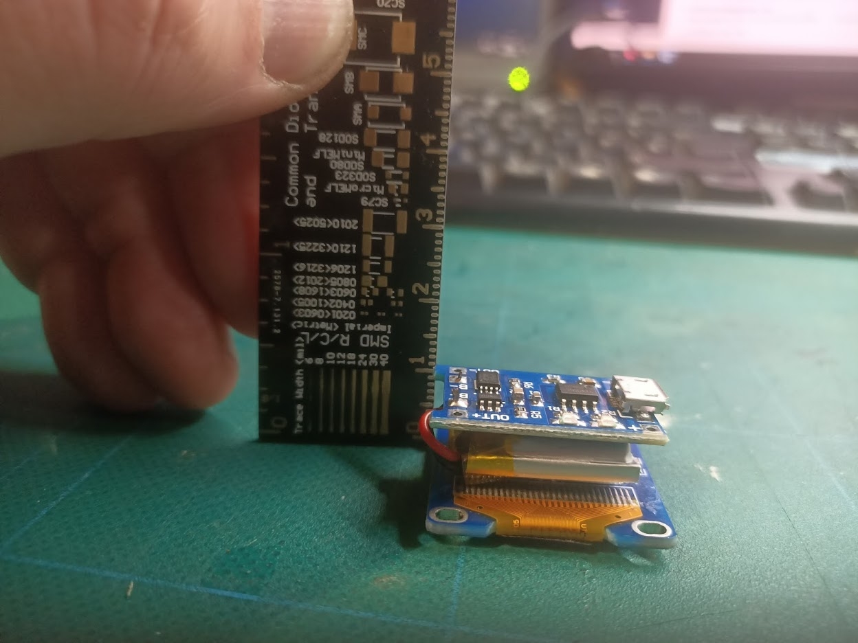
Our components basically consist of an LCD (bottom) a 100mAh lipo rechargeable battery (middle) a USB charging circuit (top) to safely recharge the battery from any mobile phone type charger, and the control circuit (an Atmel AVR TQFP chip on a custom circuit board – not shown)
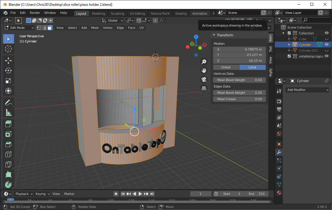
Taking these measurements, I drew a basic cube shape in Blender (to indicate the void space needed) and expanded it a bit.
Then I added various cubes and cylinders around it, and used multiple “boolean” operations to create a simple shape that could be 3d-printed on my AnyCubic Photon resin printer (the fdm-printer is currently being rebuilt).
Lastly, I drew the OnTableTop logo in Inkscape and extruded it as a series of 3d shapes, to recreate the logo on the front of the enclosure shape
Then it was off to the printer! And a four-hour wait while three of these things slowly emerged from the vat of gloop…..
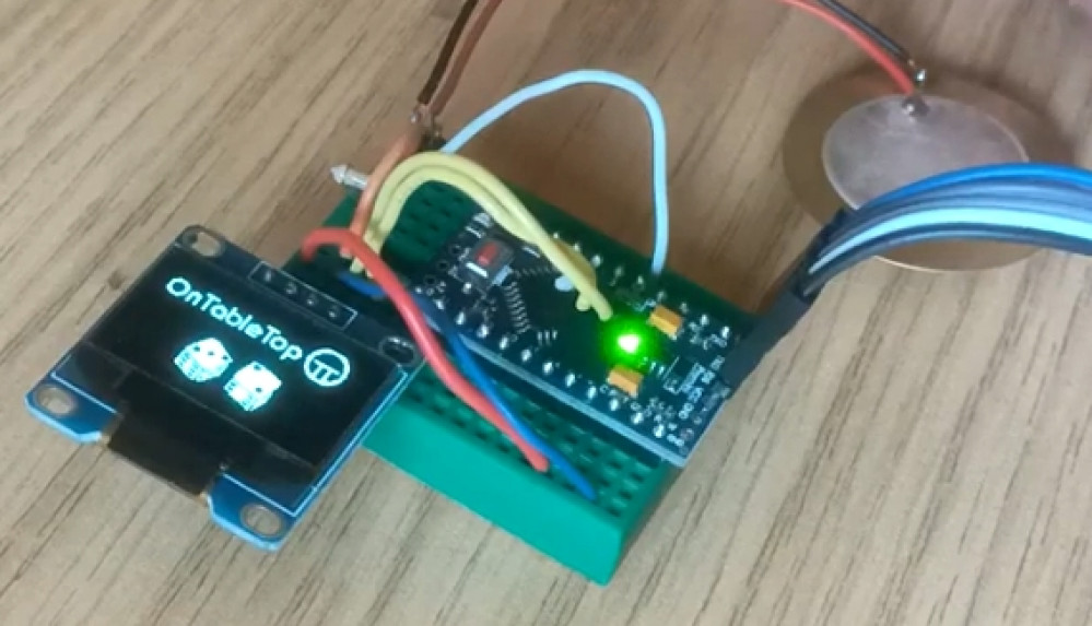
Testing our dice roller
Here’s a demo of our electronic dice roller. The device has the piezo sensor connected to an “external interrupt” pin which can be used to wake the microcontroller from “deep sleep” (this means that after a period of inactivity, the device can shut down to conserve battery resources, but doesn’t need to be switched on or off via a switch between uses).
The basic premise is this:
When the interrupt first happens (the piezo is tapped) a timer is set running. If a second tap is detected before this timer hits 500 milliseconds, the device knows to roll two dice; if no second tap is detected, a single dice is “rolled”.
To roll the dice, a pseudo-random number is generated.
Within the Arduino library exists a pseudo-random number list; it’s basically a set list of numbers and each time you call the rand() function, the next number off the list is returned. Not so random, huh??
So whenever a dice roll is required, we sample the (floating) voltage from a disconnected pin and use this, along with the number of milliseconds that the device has been running, to determine where in this list of numbers we draw our next value from.
Since the analogue voltage on a disconnected pin is basically picking up atmospheric static, this means our seed number will always be some kind of random value; but even if perfect atmospheric conditions existed, and this value could be determined, by using the “milliseconds since start” it’s almost impossible to predict the starting point in the random number list – thus ensuring that the dice roll value returned is more or less truly random.
Now we’ve got it working, it’s time to miniaturise everything and try to squeeze it into an enclosure.
Let's see what we're doing
“The internet” is awash with cheap electronics components. If you know what you’re looking for, of course. And I’ve already had experience of working with some tiny little LCD screens but had a real time finding them. Until I stumbled upon the correct search term – “oled spi” and “oled i2c” (I forgot they’re oled, not LCD).
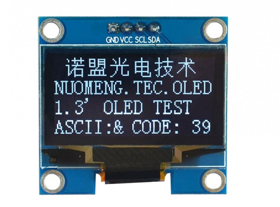
These little things are brilliant for displaying small amounts of data (I used to use them to display the IP address of internet-connected cameras) and, thanks to the user-friendly Arduino libraries, are really easy to interface with.
Using just two wires (plus power and ground) and the Adafruit_SSD1306.h library, it took just ten minutes to get some custom text to appear on the LCD screen.
And then not really that much longer to embed my own bitmap code, to create pretty pictures too…
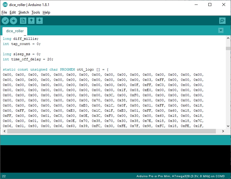
And just like that, all the pieces were suddenly in place for creating a tap-to-active dice roller.
I could create the bitmaps I wanted, I could get them to display where I liked on the screen, and I had a tap-to-trigger input system that I could use to tell the device when I wanted another number selecting.

Refining the design
Now, we’ve got a fully protected, give-it-a-whack-to-create-a-digital-signal system here. And if we feed this voltage signal into a microcontroller, we can use it as a trigger (in this case, to say “hey, generate another dice roll, will you?”)
But there’s just one other thing to consider – remember that graph showing the output of a piezo when you give it a wallop?

We’ve filtered out the negative voltages. And we’ve clipped the input voltage so it can’t exceed 5V. But there are still lots of signals, each getting smaller as the signal decays, all in very close proximity to each other.
We can get rid of these by introducing a “sensitivity filter” – simply put, we can connect the lead with the generated voltage in it back to ground, through a resistor.
The smaller the resistor, the more easily current can flow through it – so a small resistor means that you need to give the piezo a real whack for any of the voltage to reach our microcontroller input (since the generated voltage would much prefer to go to ground that through a whole series of transistors and complicated logic gates that makes up a microcontroller).
A large value resistor makes current flowing through it difficult, so some of the signal will go to the microcontroller and some of it will pass through the resistor to ground. The larger the value, the more of the signal reaches the microcontroller. The smaller the value, the more of the signal just gets dumped to ground.
In practice a resistor of about 300K (300,000 ohms) is a nice “filter”. It means that a large part of the first, largest “wave” from the generated voltage reaches the microcontroller input pin. But the smaller “ripple” waves pass more easily through the resistor and dissipate to ground.
A resistor of 100K would still work (but it means you have to give the piezo a real clatter for any of the generated voltage to reach the input pin). It effectively “deadens” the piezo as a voltage generator. A resistor of 1M (1,000,000 ohms) means that most of the signal reaches the microcontroller, so the piezo is very sensistive (and creates a lot of signal voltage, even from a very small tap).
Now we could just choose a resistor value, through trial and error, and hope that everyone taps the piezo with a similar amount of force to activate it. And this would be a perfectly acceptable way to proceed.
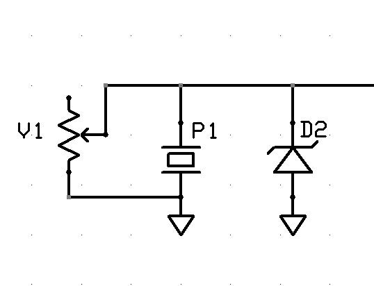
But to just refine our design that little bit further, we can replace the fixed value resistor with a variable resistor or potentiometer.
This provides a means of changing the amount of resistance cross two terminals, allowing the end user to set their own preferred degree of “sensitivity”. Giving us our final piezo-input circuit:
Give it a whack
What happens when we give a piezo a whack?
It generates voltage. Maybe only a tiny amount. Maybe quite a large amount. It depends how hard you whack it. Although the current may only be a few milliamps, the voltage can be in the tens of volts

The voltage also goes positive and negative. And repeats, as the signal decays. Give a piezo a hard enough whack and a single hit can produce four, five, six or more detectable “peaks”.
Now microcontrollers (into which we’re planning on feeding such a signal) are sensitive little things (especially the AVR chips that make up the hobby-friendly Arduino development platform) and really don’t like too high a voltage being pushed into them, and they really, really don’t like negative voltages (PIC microcontrollers, with their “clamp diodes” on the i/o pins are far more robust, but we’re sticking with AVR to keep the project “hobbyist friendly”).
So we need to do two things to this signal – prevent any negative signal from reaching our microcontroller, and peaking the voltage at about 5v.
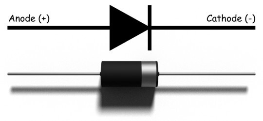
This is a diode. It’s a component that only lets current flow in one direction. It allows current to flow from the anode (positive) to the cathode (negative) terminals, but blocks any negative voltage trying to flow back the other way (hence the little “barrier” mark on the symbol, to indicate that current will be blocked).

Now the above is a very simplified analogy and while not strictly true for the pedants who might want to argue against it, it serves the purpose to demonstrate that positive voltage flows easily through a diode from anode to cathode, but negative voltage cannot.
Interestingly, it is possible for negative voltage to flow “backwards” through a diode (negative voltage on the cathode, marked -ve, can flow through the diode towards the anode, marked +ve).
We can make use of this property, and a special kind of diode to help us achieve our aims: with a zener diode.
Zener diodes are special in that they act like normal diodes up to a specific voltage. Over this voltage, they “break down” and allow the “excess voltage” to pass through.
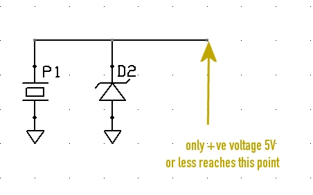
Zener diodes have specific values at which they “break down” so by placing a 5V zener diode as in the diagram above, we achieve two things:
If the piezo transducer is creating a negative voltage, this negative voltage is allowed to pass “backwards” through the diode, and will safely go to ground – it does not enter the microcontroller.
Secondly, if the piezo is creating a positive voltage (that we want to capture) any voltage above 5V will also pass through the diode, into ground. This means that the maximum voltage that will reach our microcontroller is positive, up to 5V (it can still be less than 5V).
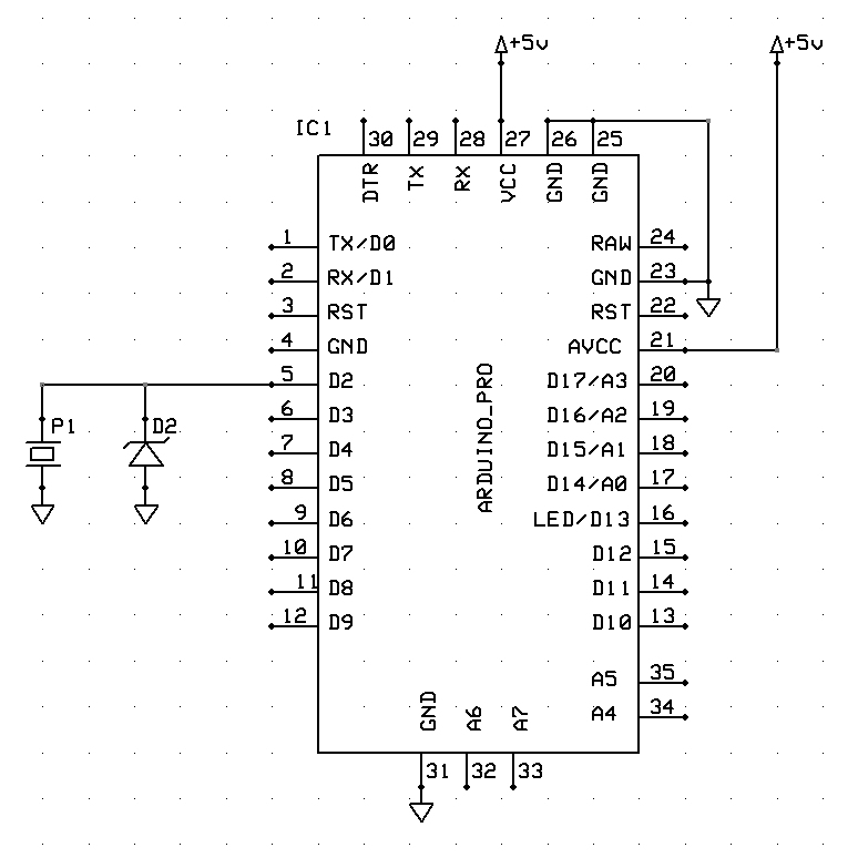
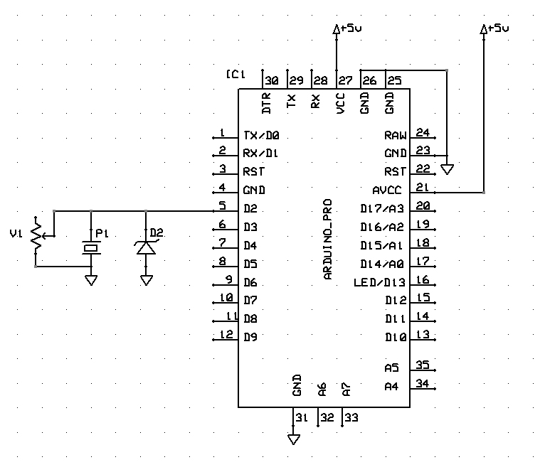
So this is how we wire the piezo to our Arduino input, ensuring that it is protected from over-voltage and negative voltage, generated by giving the transducer an almighty great whack (hey, who knows which klutz is going to be using these things?)
This is a piezo
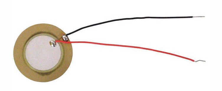
This is a piezo.
Well, to give it it’s full name, a piezo-electric tranducer. They pop up in lots of things. Mostly in anything that makes a noise.
They’re like a super-cheap alternative to a speaker (but really poor quality). Apply a voltage across the leads and the disc will refract. Do this often enough and you can create a sound. Do it at a specific frequency, and it can play a “note” (though it’s more like an electronic chirp at a specific pitch – calling it a note suggests a degree of musicality that, frankly, it doesn’t posses).
But piezos aren’t just for turning electricity into noise. You can use them to turn noise into electricity. You’ll often find piezo-electric transducers strapped to the body of an acoustic guitar.
The vibrations in the wood of the body are transferred into the disc of the piezo, which is sent to an amplifier, to create an electronic signal (you can get “proper” pickups for electric guitars, which sit underneath the strings, but “piezo pickups” are also common – even through, strictly speaking, they’re not really pickups).
I thought I’d use this property to create a digital dice-roller – some gubbins in miniature base with a battery and a screen, which chose a random number between a range (1-6 for D6, 1-10 for D10) and displayed the result as a bitmap (depicting a dice value) on a tiny LCD screen.
Such a simple object doesn’t need a fancy UI – just a way of telling it “I want a new value now, please”. I figured that tapping the object down on the tabletop would be a perfect way to trigger such a request.
And a piezo would be the perfect way of accomplishing this.