


![A Perfect Zombie Apocalypse Starter Set? Civilians & Survivors Review | Wargames Atlantic [7 Days Early Access]](https://images.beastsofwar.com/2026/01/unboxing-wargames-atlantic-civilians-_-survivors-1_2-coverimage-225-127.jpg)
![Wild Australia Wargaming? 28mm Ned Kelly Gang & Victorian Police Review [7 Days Early Access]](https://images.beastsofwar.com/2026/01/unboxing-traders-galaxy-australiana-ned-kelly-gang-_-victorian-police-coverimage-225-127.jpg)


How to be an Armoured Farmer, building Hobart’s Funnies in Glorious 15mm (and maybe 28mm if they arrive in time!)


Recommendations: 2233
About the Project
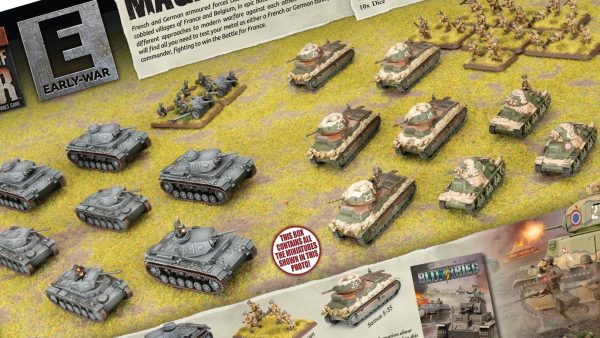
Right then, having avoided any sort of Spring cleaning challenge in the past, I have decided to use this year's one to get something done that I have been gathering bits for over the past few years and finally finish and assemble all of my Hobart's Funnies. To get technical these are Armoured Vehicle Royal Engineers (AVRE) tanks, using the Churchill chassis as a base. I will also throw in some Sherman Crabs (Flail tanks). I have gathered a few books for reference so that I can paint and mark them up for one of the Armoured Assault Squadrons Royal Engineer (either 77, or 79) that landed ashore at Sword Beach and were the very first to see action on that beach; Plus the Sherman Crabs of A Squadron 22nd Dragoons. Whilst I want to be able to use the finished tanks in games depicting the D Day Landings (in Flames of War and Chain of Command at 15mm) I also want then to be versatile enough to be able to be used in later engagements that the 79th Armoured Division took part in (which is pretty much everything!). I hope you will find this of interest if you ever want to branch out into what the modern day Royal Engineers affectionately call being an armoured farmer.
Related Game: Flames of War: The World War II Miniatures Game
Related Company: Battlefront Miniatures
Related Genre: Historical
Related Contest: Spring Clean Hobby Challenge (Old)
This Project is Active
Building the Small Box Girder Bridge Layer (SBG) cont'd (the last bit)
The last couple of bits were to clean up and assemble the winch unit that sits on the back of the tank. This was so simple to build that I forgot to take photos of it!
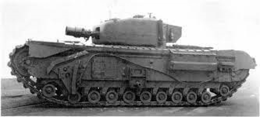
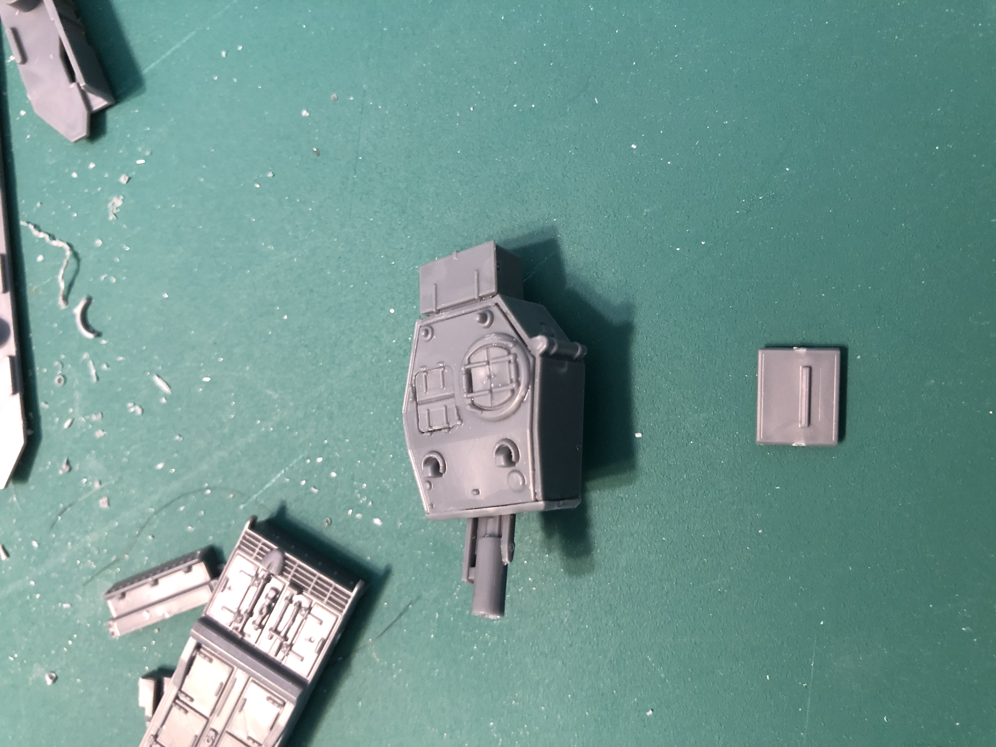
Next was to assemble the turret, I selected a Mk III turret as this matched all of the reference photos I had. Two points to note with this turret, firstly the petard mortar is a VERY tight fit in the gun mantlet, so much so that you may bend or break them if you are not careful. Secondly, the rear turret piece has a bar on it for fixing the back bin to. Make sure that it is in its lowest position in relation to the the turret top, or you will end up cutting it off and eyeballing where the bin should be fixed to the turret.
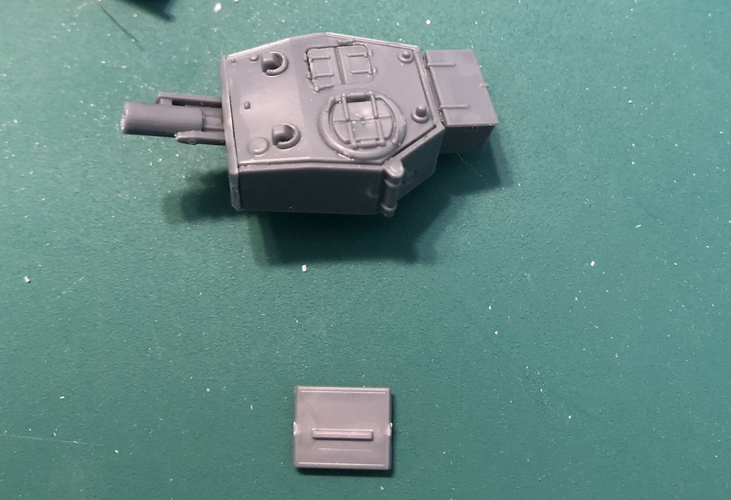 Right way up
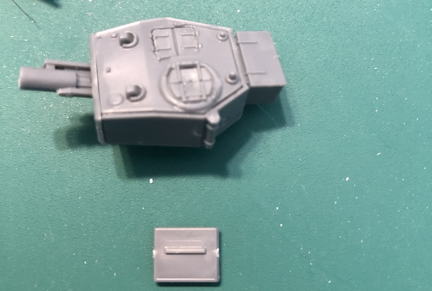 Wrong way up!
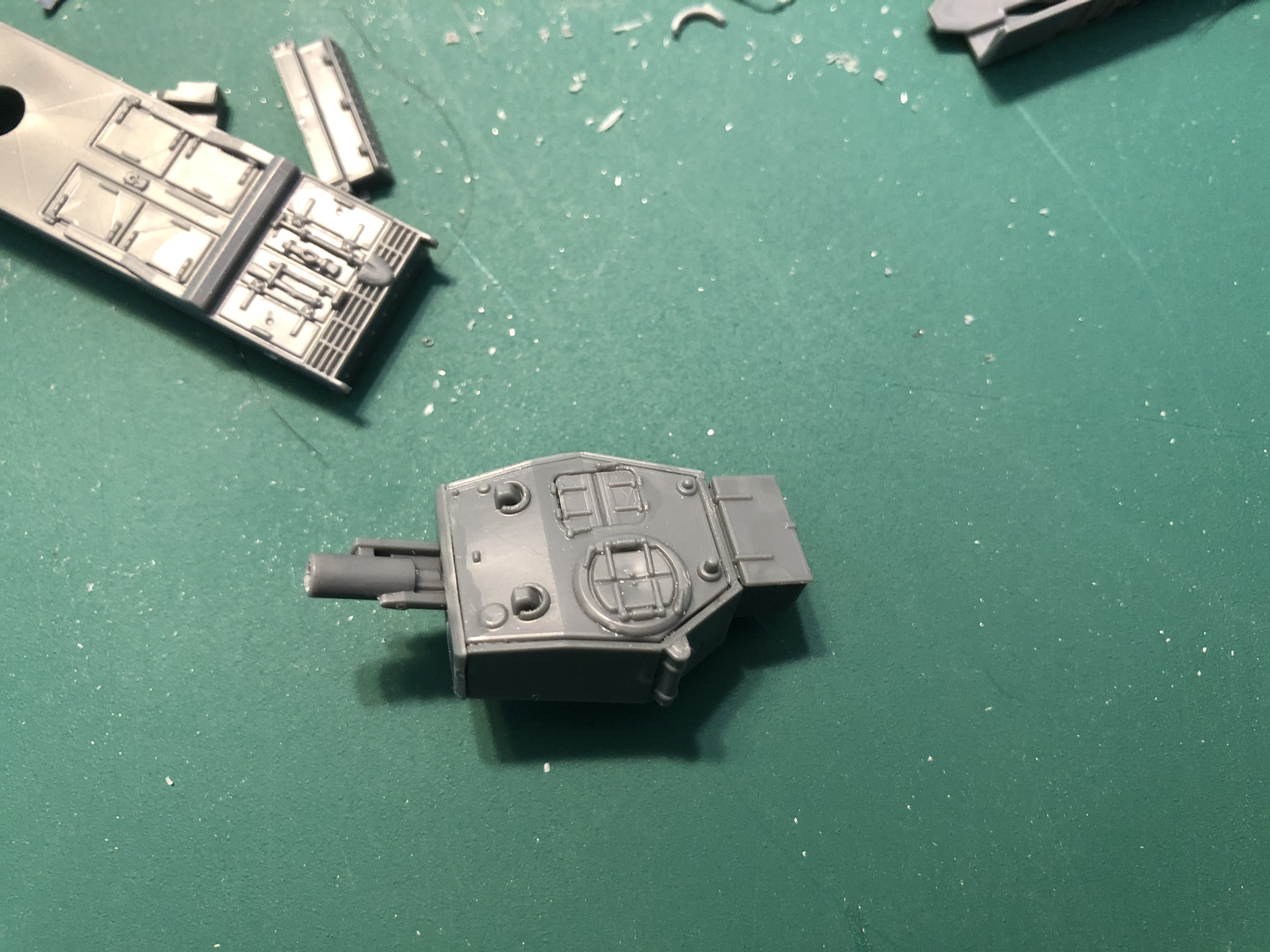 Finished Mk III turret
Building the Small Box Girder Bridge Layer (SBG) cont'd (the last bit)
With the bridge built, glued together the cradle that houses the winch at the back of the tank. It was very simple to build (so simple I forgot to take any photos of it!) The only other difference from building the other AVREs was that for this one I had chosen a Mk III turret. This was because all the reference photos I have of a bridge layer are of the Mk III variant of Churchill. The two things to note with this turret build are that firstly, the petard mortar is a VERY tight fit into the turret mantle, so be careful as you may bend, or break either one. the second is that the rear plate on the turret has a mounting bar for the back bin. It is not shown on the instructions but make sure that the bar is in its lowest possible position it relation to the top of the turret, or, like me you will end up having to cut it off to get the back bin to sit right on the turret.

 Right way
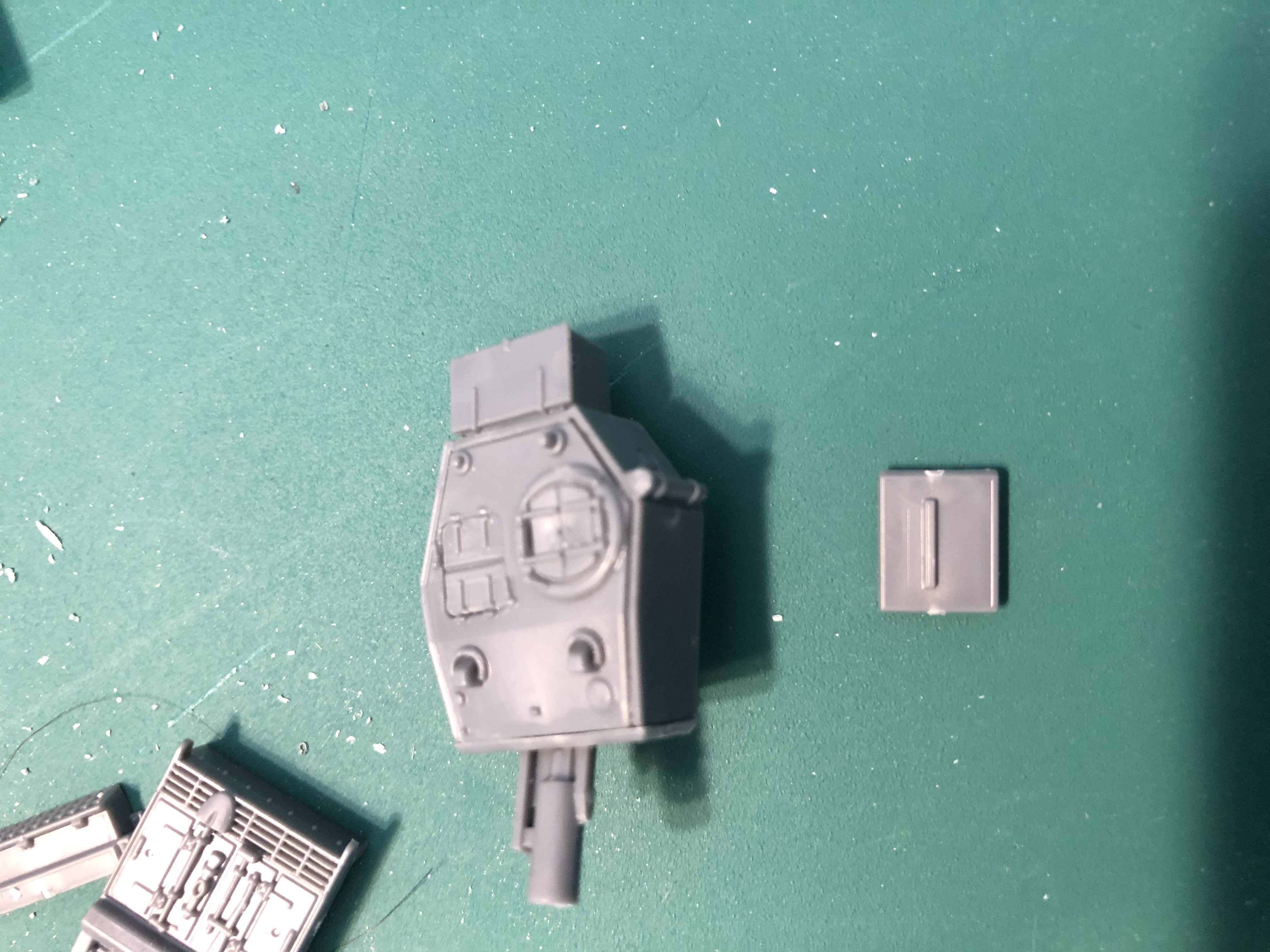 wrong way!
Building the Small Box Girder Bridge Layer (SBG) cont'd (blimey how much longer?!)

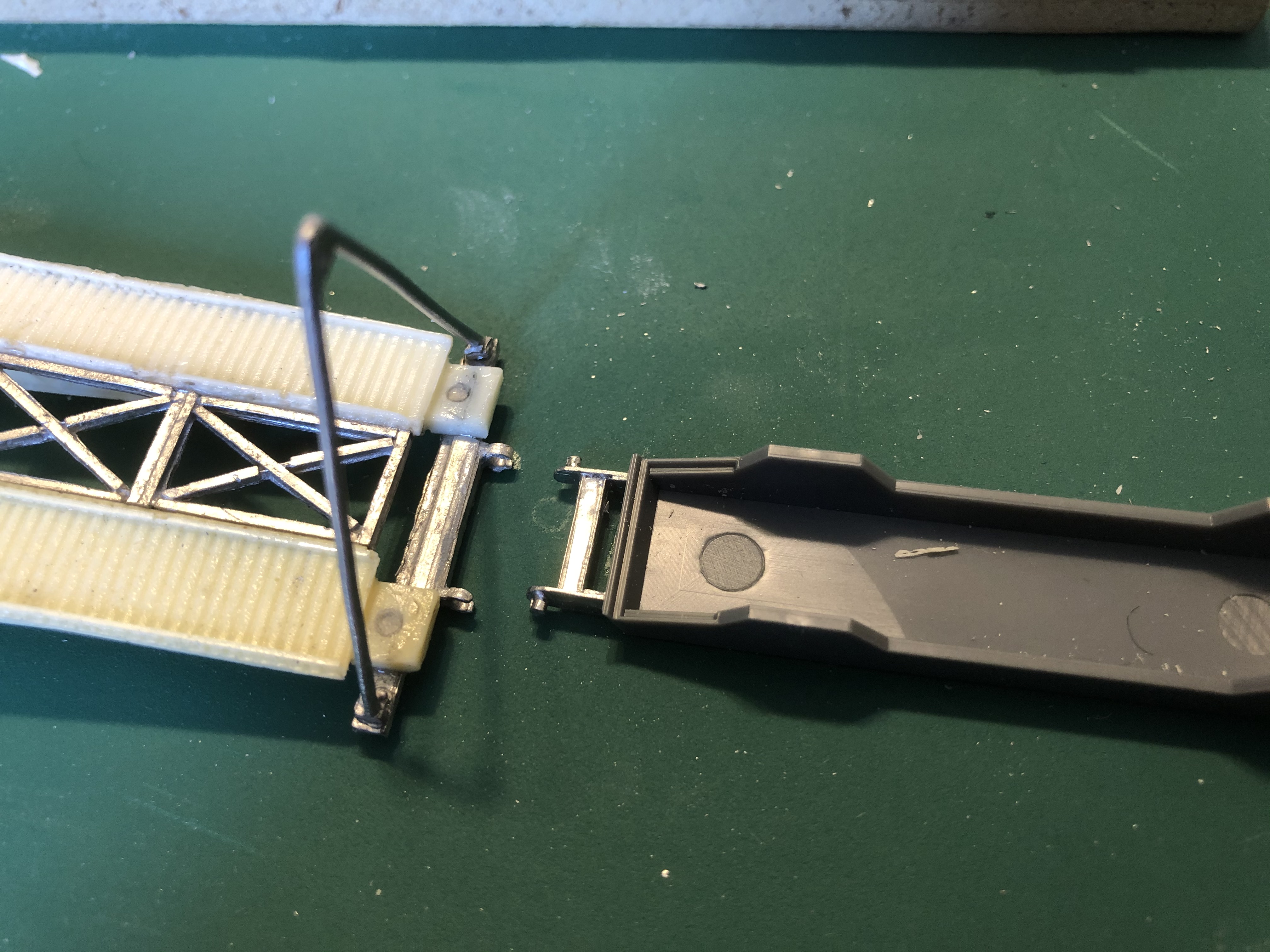
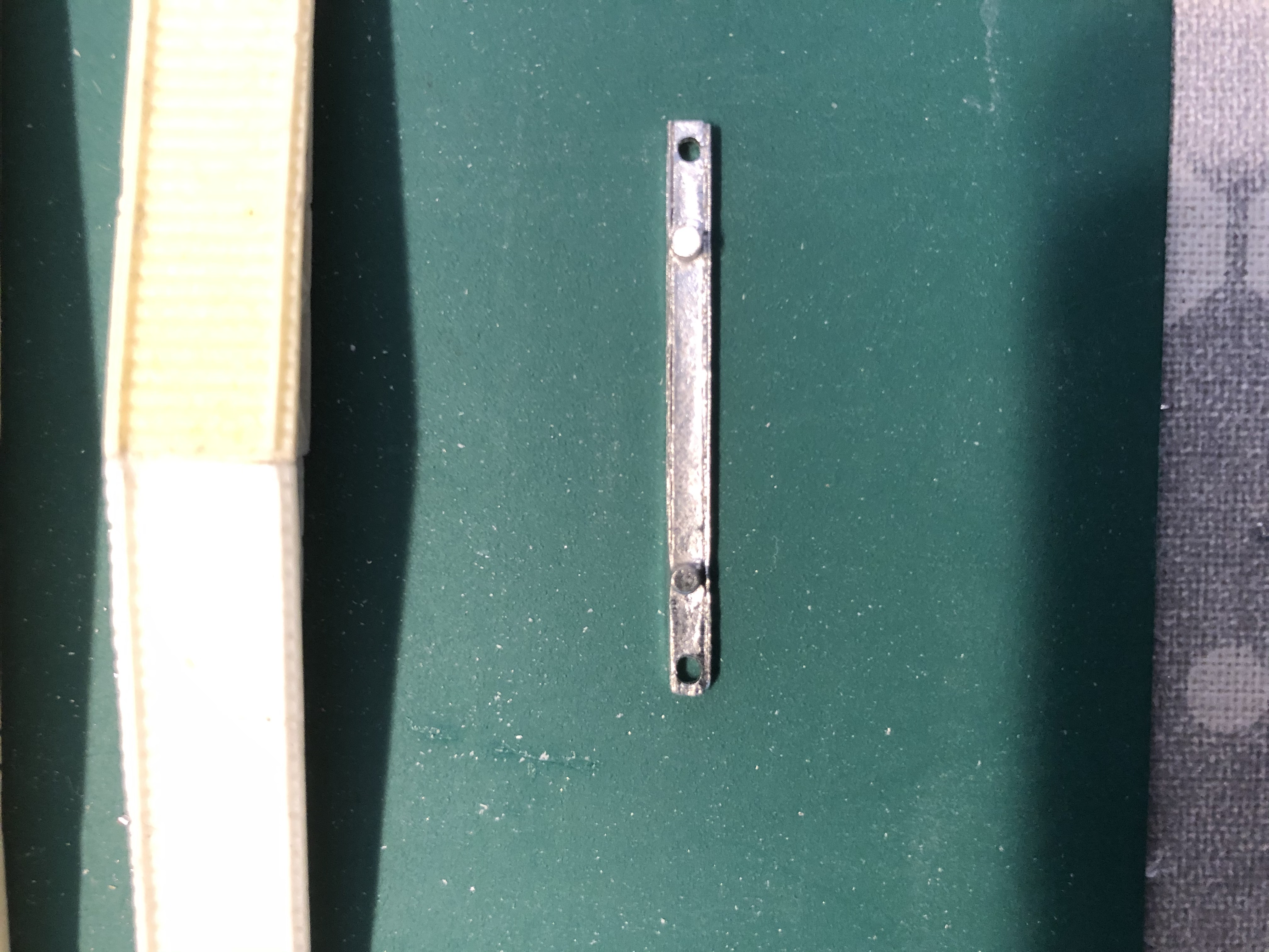
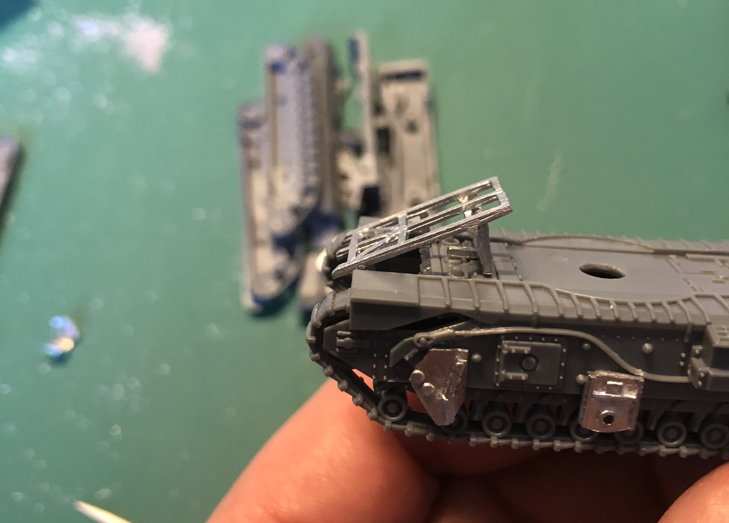
The last bit for the bridge was to attach the A frame. This had predrilled holes for it to fit into on the bank seat beam and in real life is there to act as a fulcrum for the cables that lift and/or lower the bridge into place (more on that in a later post). The white metal was slightly bent in the post but easily straightened out and glued in place. I had decided early on that one of the bridge layers would be built carrying its bridge and the other one left loose so that I could leave it in place in games. As the resin one is very light compared with the SkyTrex version I chose this one to fix to the AVRE. What also helped was the fixing points between the tank and bridge were better, so that I could guarantee a good link between the two. The actual A frame is in two parts and once realised the two sides of the frame would fall off to either side to not impede the use of the bridge. Once the battle had moved on, engineers could come back and remove the frame sections for use on another bridge, or the bridge would be replaced with a more permanent bridge using either Bailey, or other readily available materials (this type of bridging is called NEB (non equipment bridging) and uses such materials as tree trunks & steelwork from nearby buildings etc. to construct a bridge).
Building the Small Box Girder Bridge Layer (SBG) cont'd (a bit more)

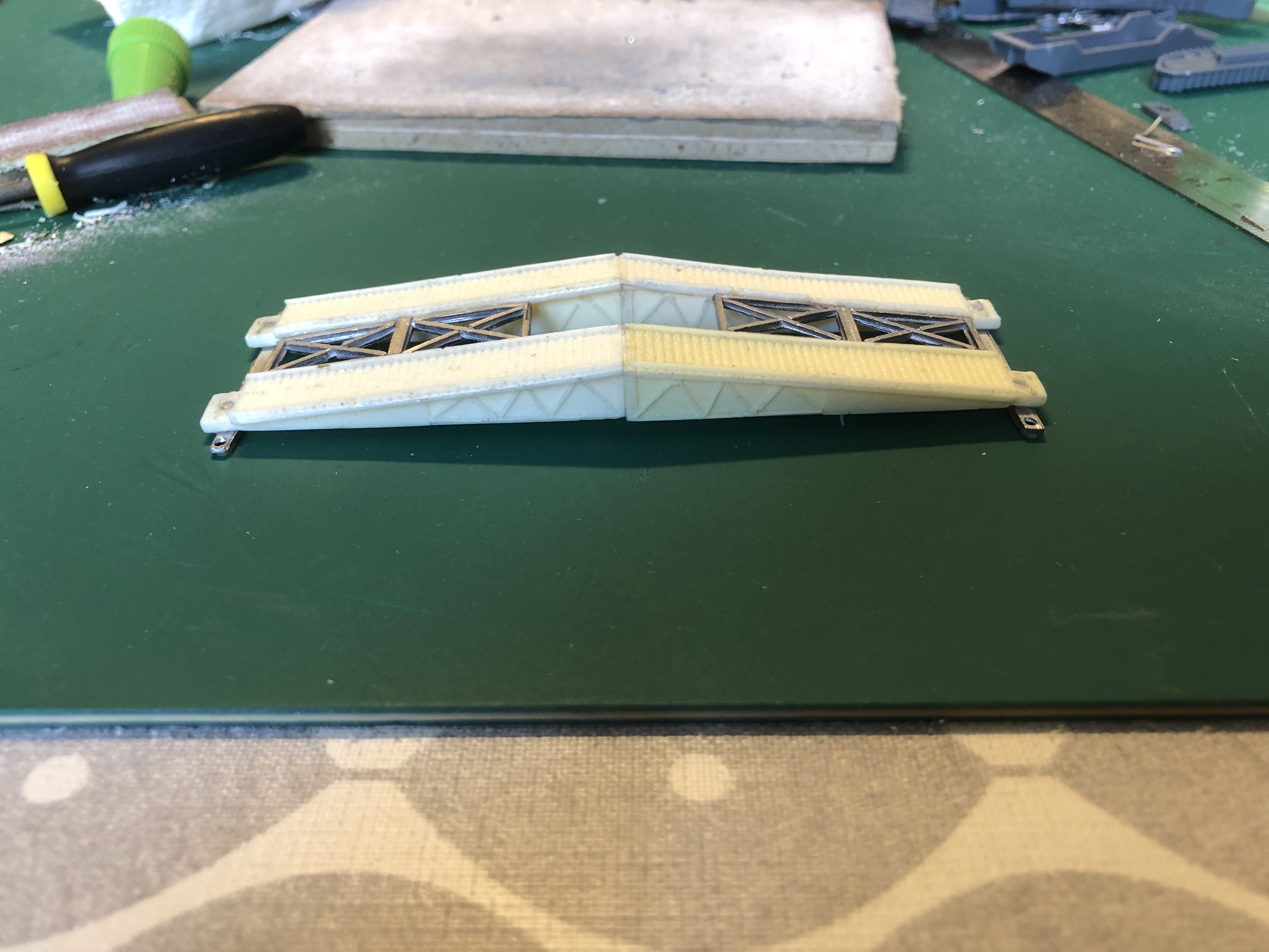
With the beams in place (or so I thought) I then filed down and trial fitted the bracing (known as either cross, or sway bracing depending on which engineer you talk to). This was again slightly tricky to do as one side of the resin ramps had a wide lip to glue to and the opposite side was a lot narrower. once correctly filed down they fitted in really well and added additional support for the model (just like in real life!). You will notice that at some point in doing the bracing is when I realised my mistake. What is written here is a much abridged version of what happened:
Oh what,
Oh no!
Bugger.
Bugger!
*^!£(*&%!(&$!(£&$(&!$(!£)*(&!&^)*&!£^)*^$^%£%$%^ BUGGGGER!!!
About 45 mins later you have the completed bridge. Easy really.
Building the Small Box Girder Bridge Layer (SBG) cont'd
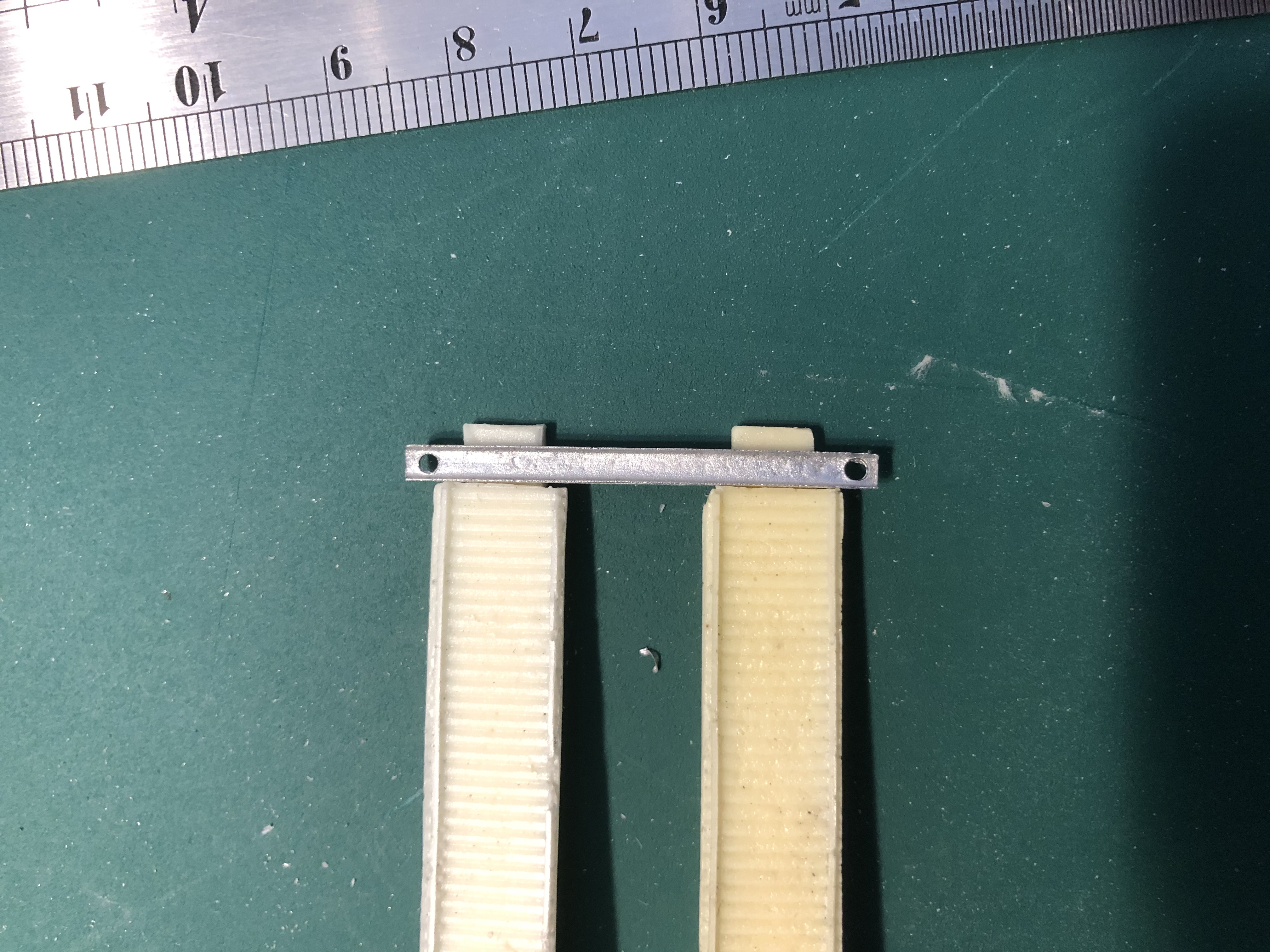
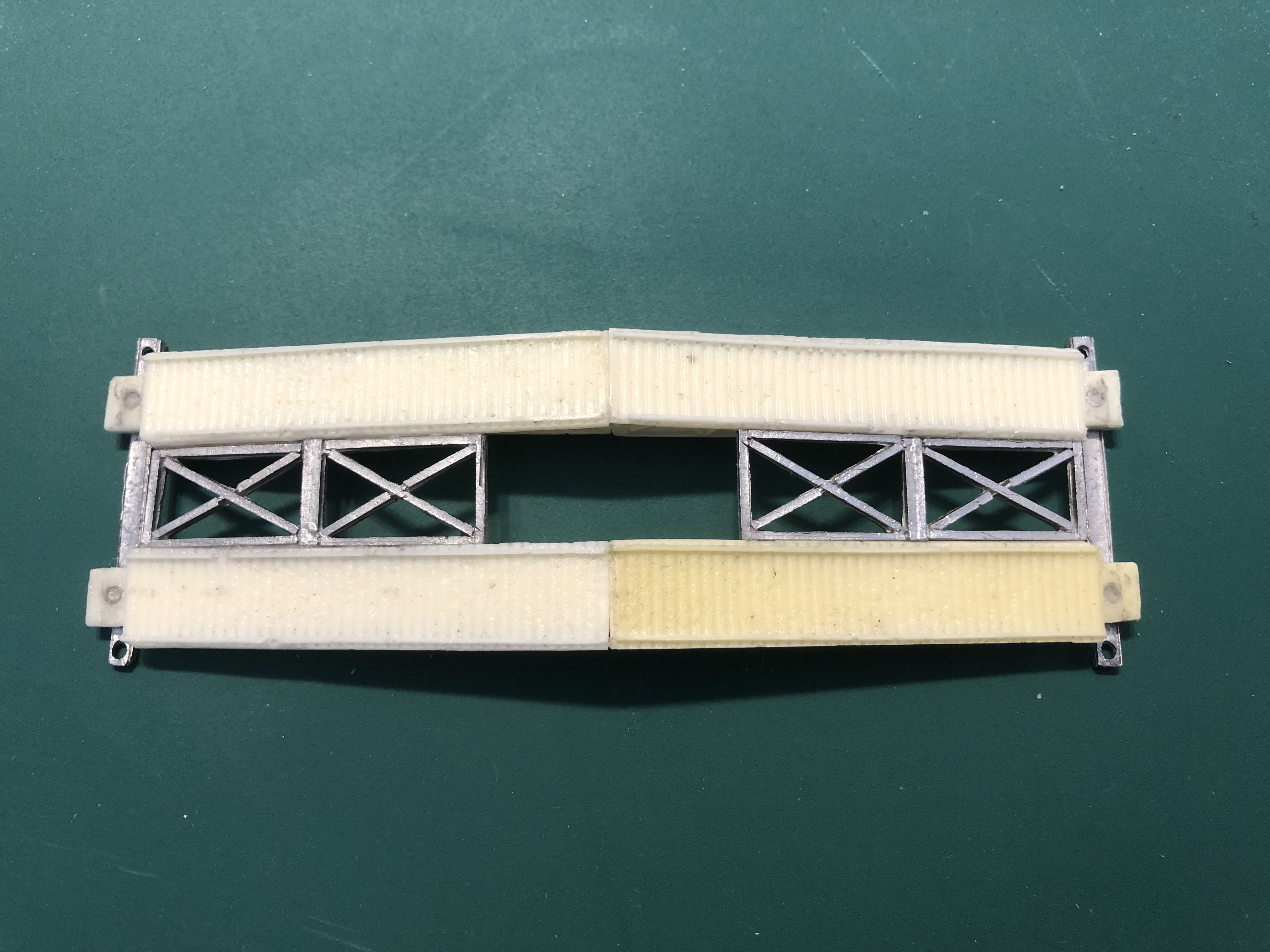
Having cleaned the flash off the two bank seat beams I trial fitted them to the bridge sections and when happy aligned them using a straight edge and glued them in place. I think/thought they looked right so didn’t bother to check the reference photos and only realised afterwards that they should have gone underneath and not on top of the bridge ramps! BUGGER!!
Brucey Top TIP
Looking right isn’t always necessarily going to be right, always check first before gluing in place, because it’s an absolute pig to sort it out afterwards!!
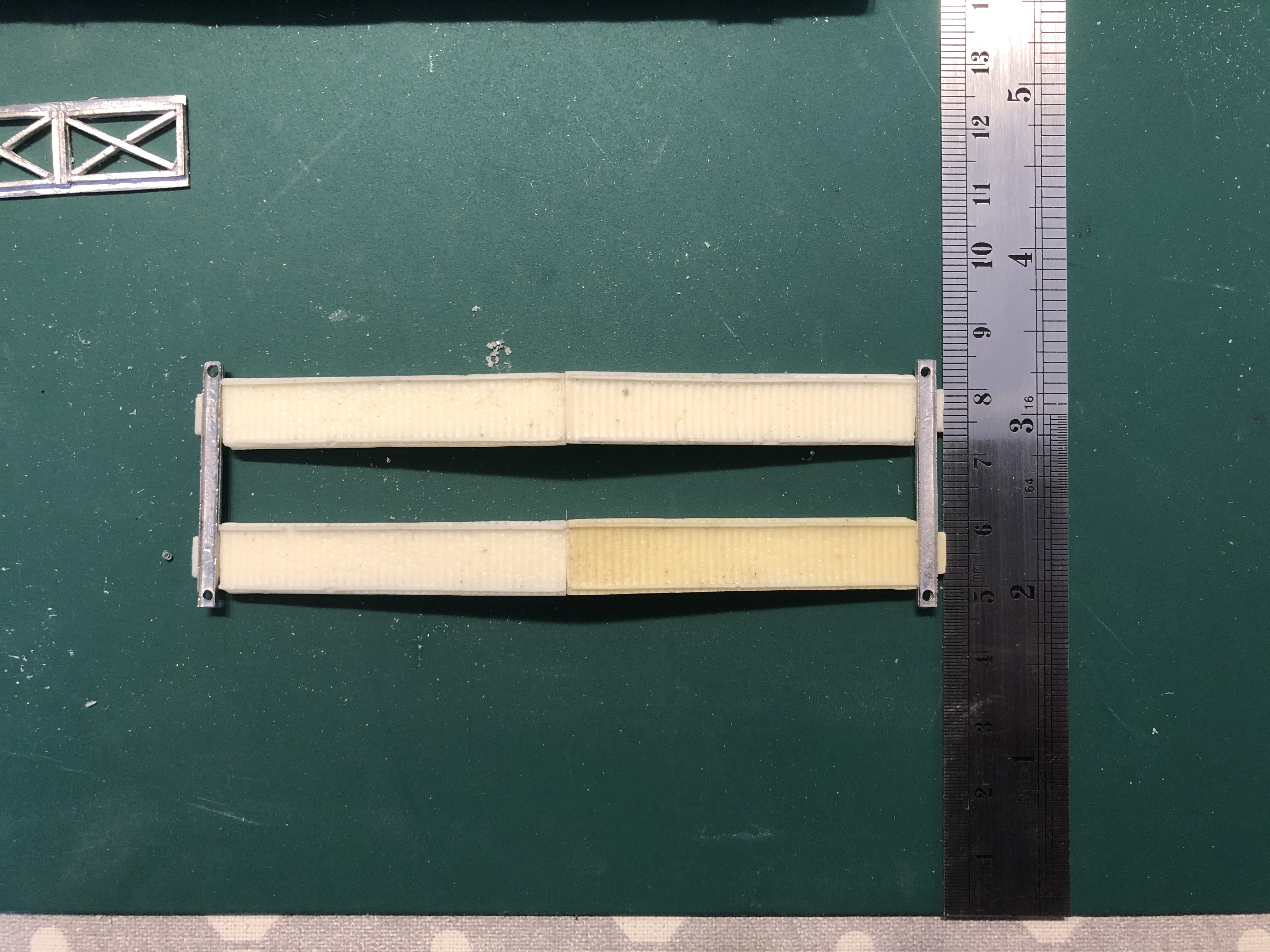
Building the Small Box Girder Bridge Layer (SBG)
The first thing to note for all the rivet counters out there in gaming land, is that this is not an SBG in the truest sense of the term, if it was it wouldn’t have a flat bottom to the bridge but would be at the same inverse angle as the top (to make an elongated diamond shape). The metal SBG I got hold of from SkyTrex is a true SBG. so what about this one, well from the evidence I can find it is a scissor bridge (folding) variant of and SBG, what I cannot confirm is whether they landed on D Day. all of the photos that exist only show the fixed bridge variants, so this type was more likely to have been used further in land. I have to be honest and state that this one, whilst I think it looks the best out of the two bridge layers I have bought, was definitely the most fiddly to put together. Also note the deliberate mistake I make with the Bank Seat Beam (the bits on the end of a bridge that actually sit on the river/gap banks). I still think it looks better the way I first did it, even though I know exactly why and how they should have been the other way around. And being a minor league rivet counter, I couldn’t just leave it being wrong, so a lot of swearing and careful scalpel work later I managed to swap them around.
So on with the build.
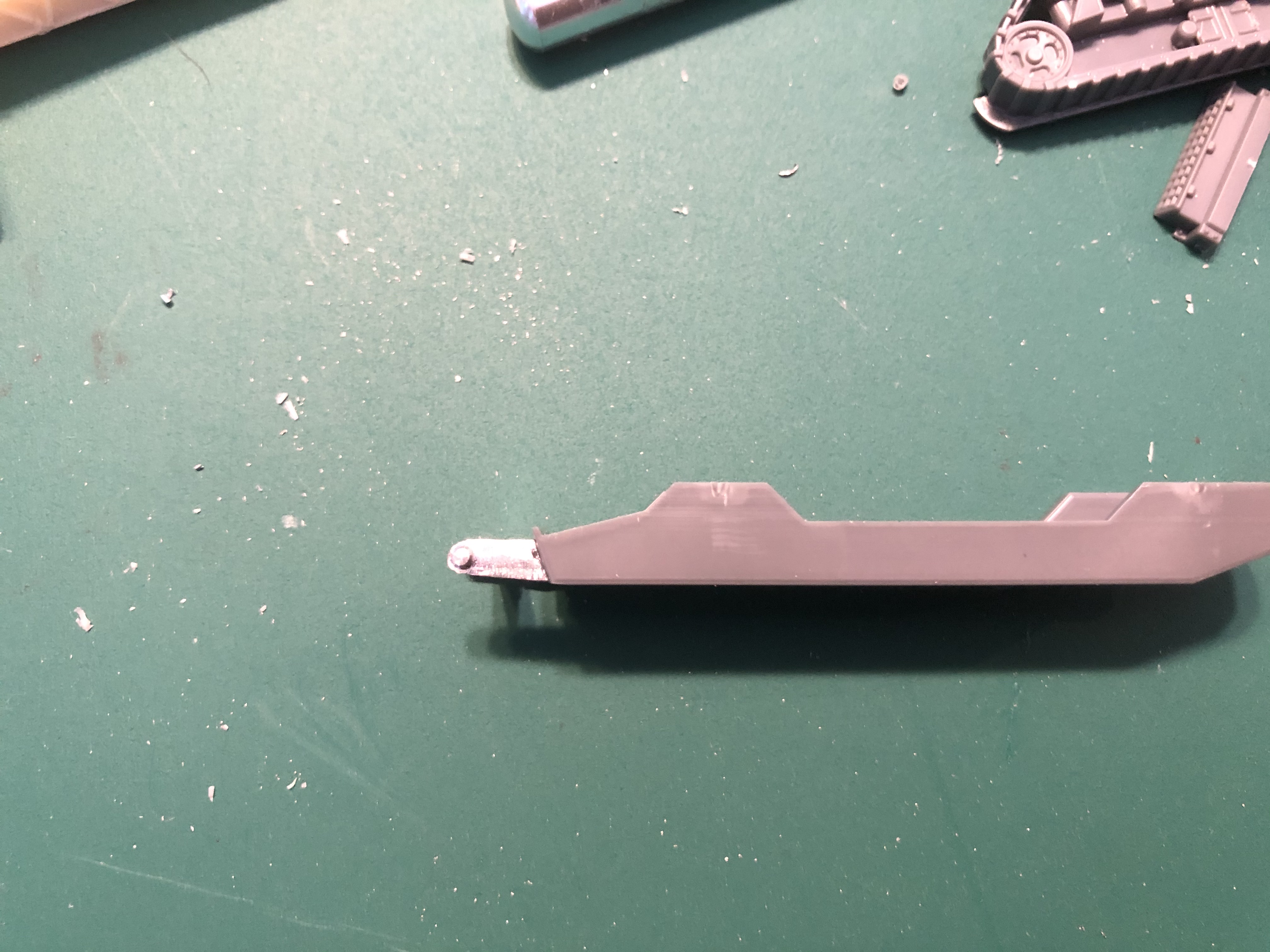

The first thing I did was to fix the bridge mounting hardpoint to the front of the hull of the AVRE. I did it now so that I had easy access for any adjustments/filing to get the best fit possible (as it will be taking all the weight of the finished bridge).
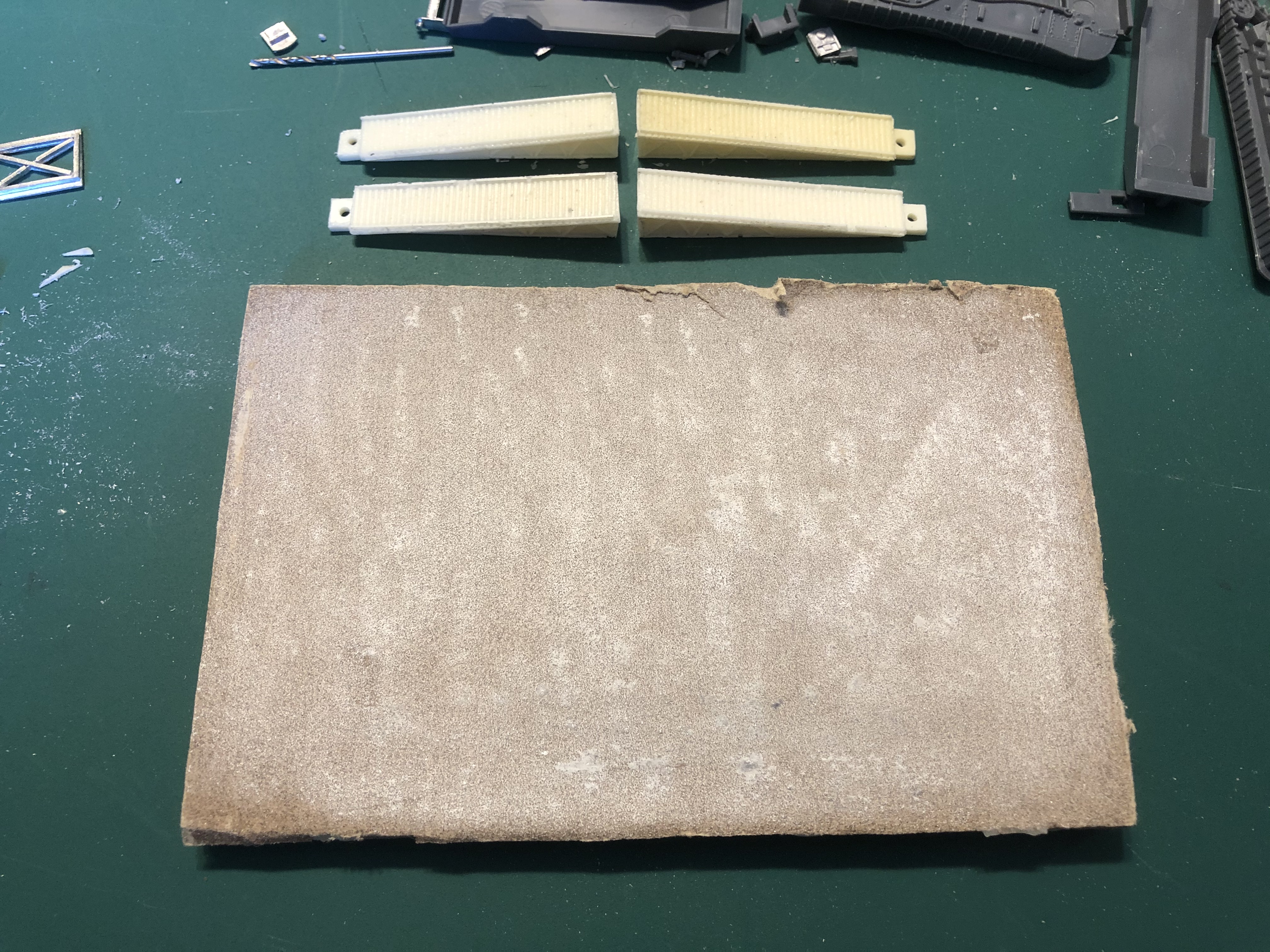
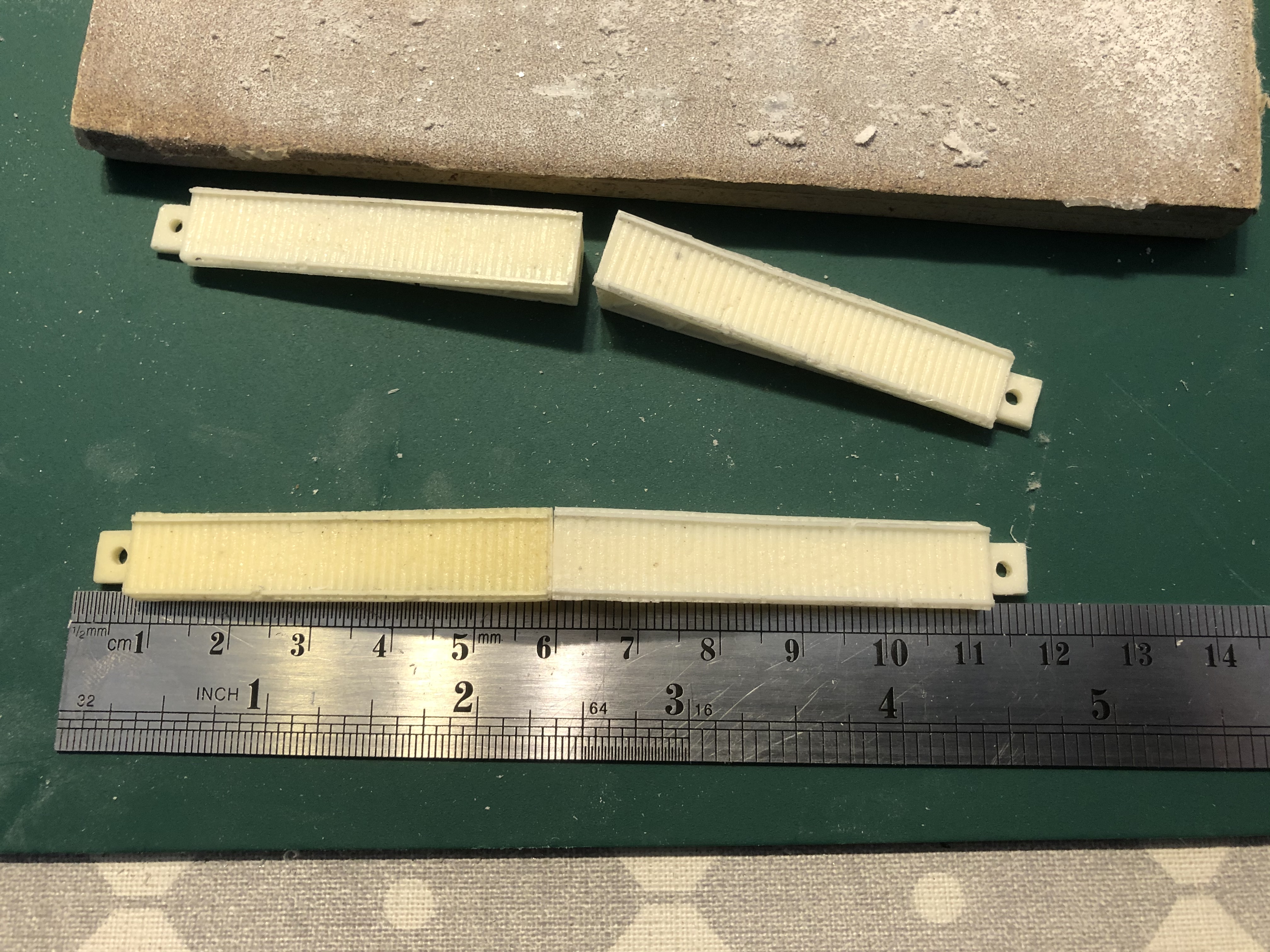
The next thing to do was clean down and sand straight the four bridge ramps. i used a straight edge and ruler to make sure that each pair would be the same length and kept checking to ensure any sanding I did was square so i ended up with mated surfaces for gluing together with gorilla glue.
Fascine Variant
The S&S fascine carrying variant consists of a Fascine (obviously!) and the cradle which fits on the front of the AVRE. In real life this cradle was mounted at an angle to allow the fascine to roll off the front of the tank once the securing cable was released by detonating a small explosive charge. The cradle then had the ability of folding down flat so that the Petard mortar could be brought into action.
As no assembly instructions were available I trial fitted everything first. looked at photos of the finished conversion on the S&S website and also looked at reference photos for the location of the cradle on the tank.
Points to note for this kit, one of the supports for the main cradle bed has an angle to it so that it fits correctly at the turret side of the cradle. Both supports have locating stubs but do need to be bent in order for the finished cradle to sit down on the tank hull properly.
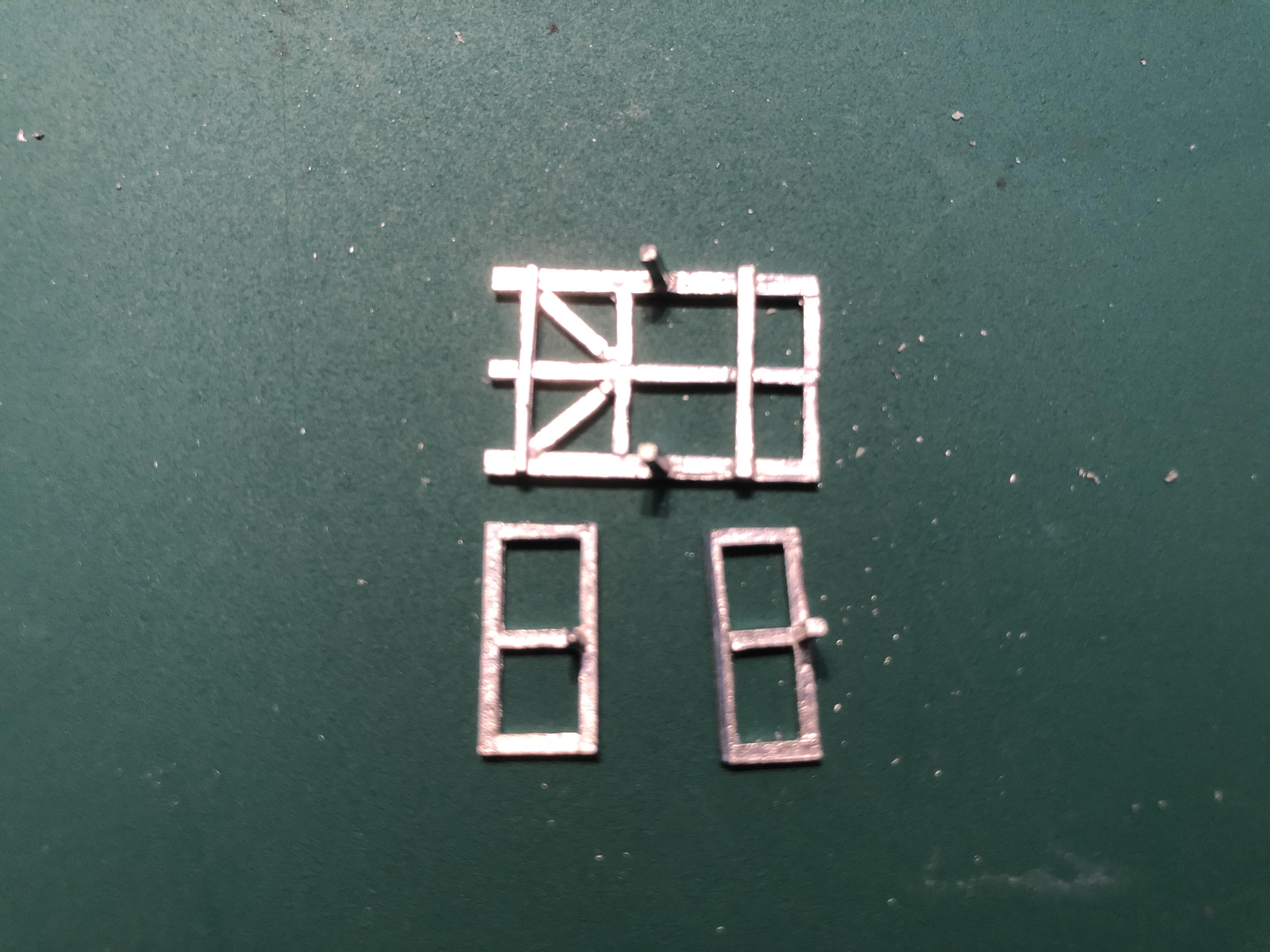 Fascine Cradle parts
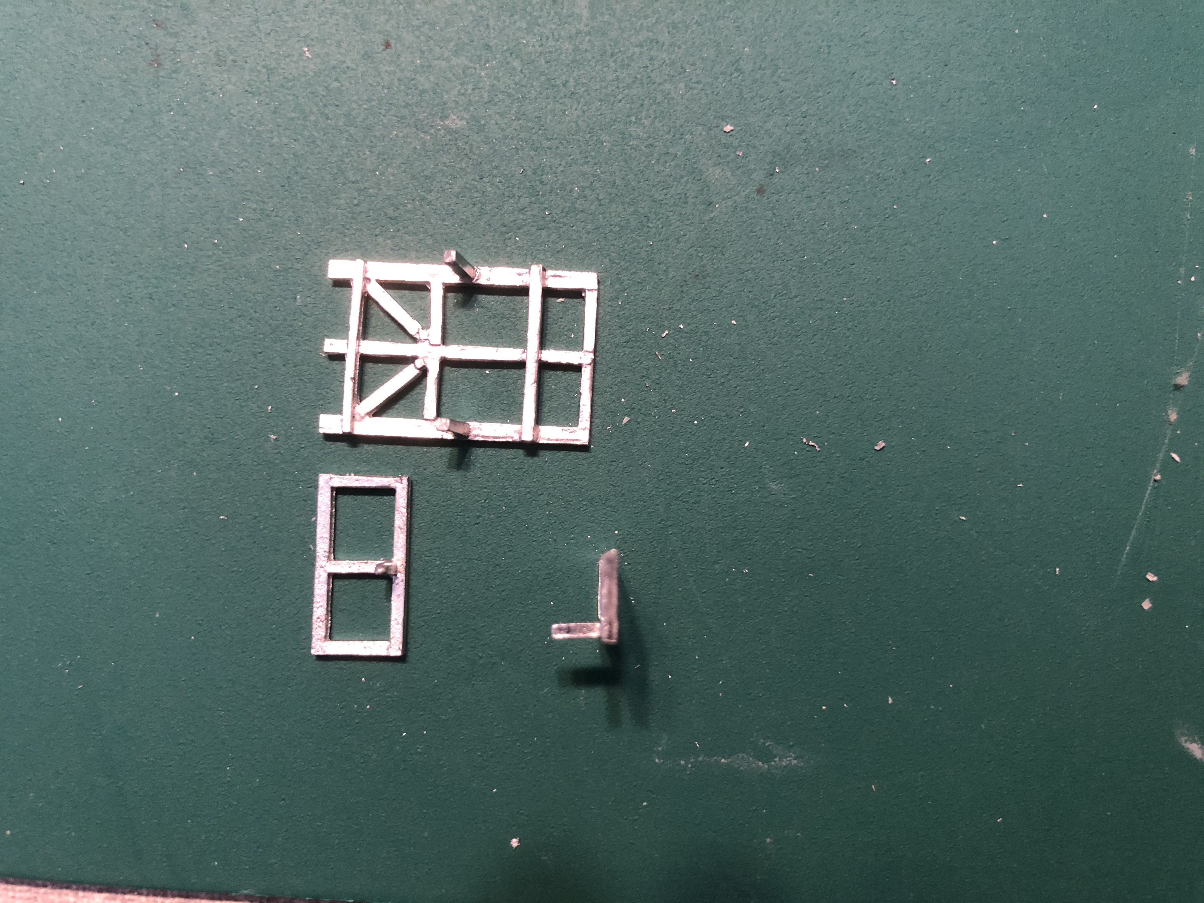 Note the angle to the top of the rear (turret side) support
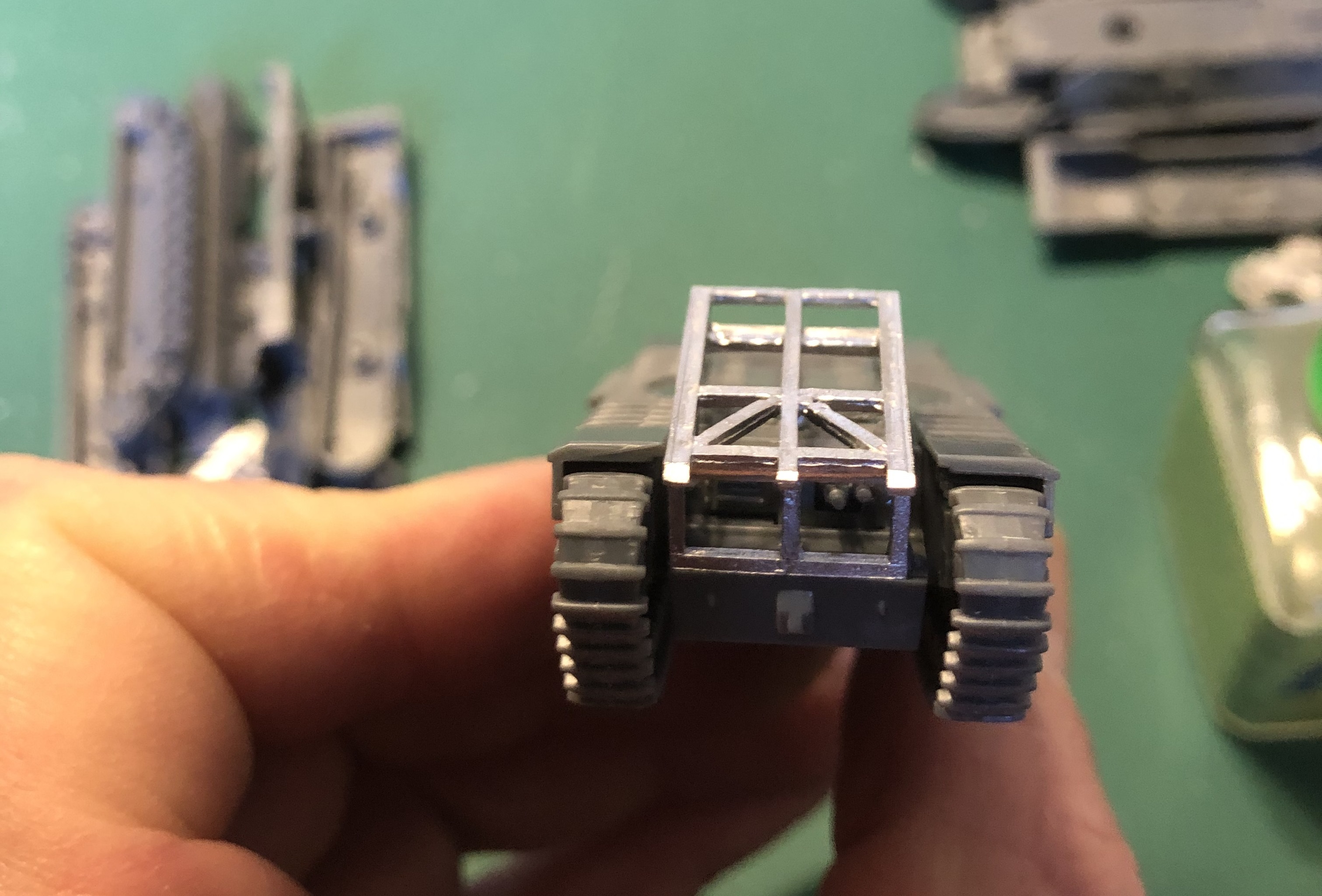
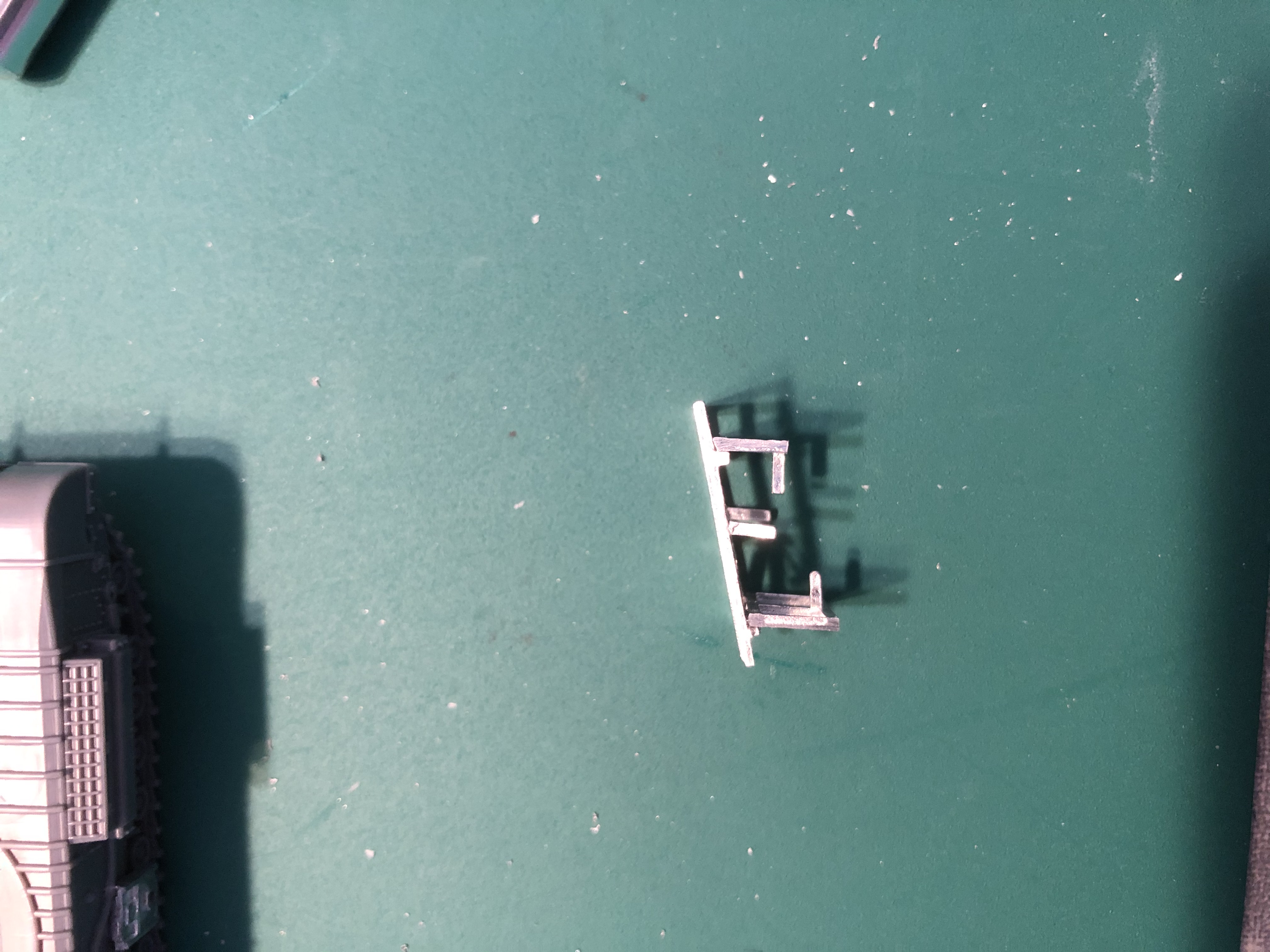 Finished cradle, note the position of the supports in relation to the cross bars.
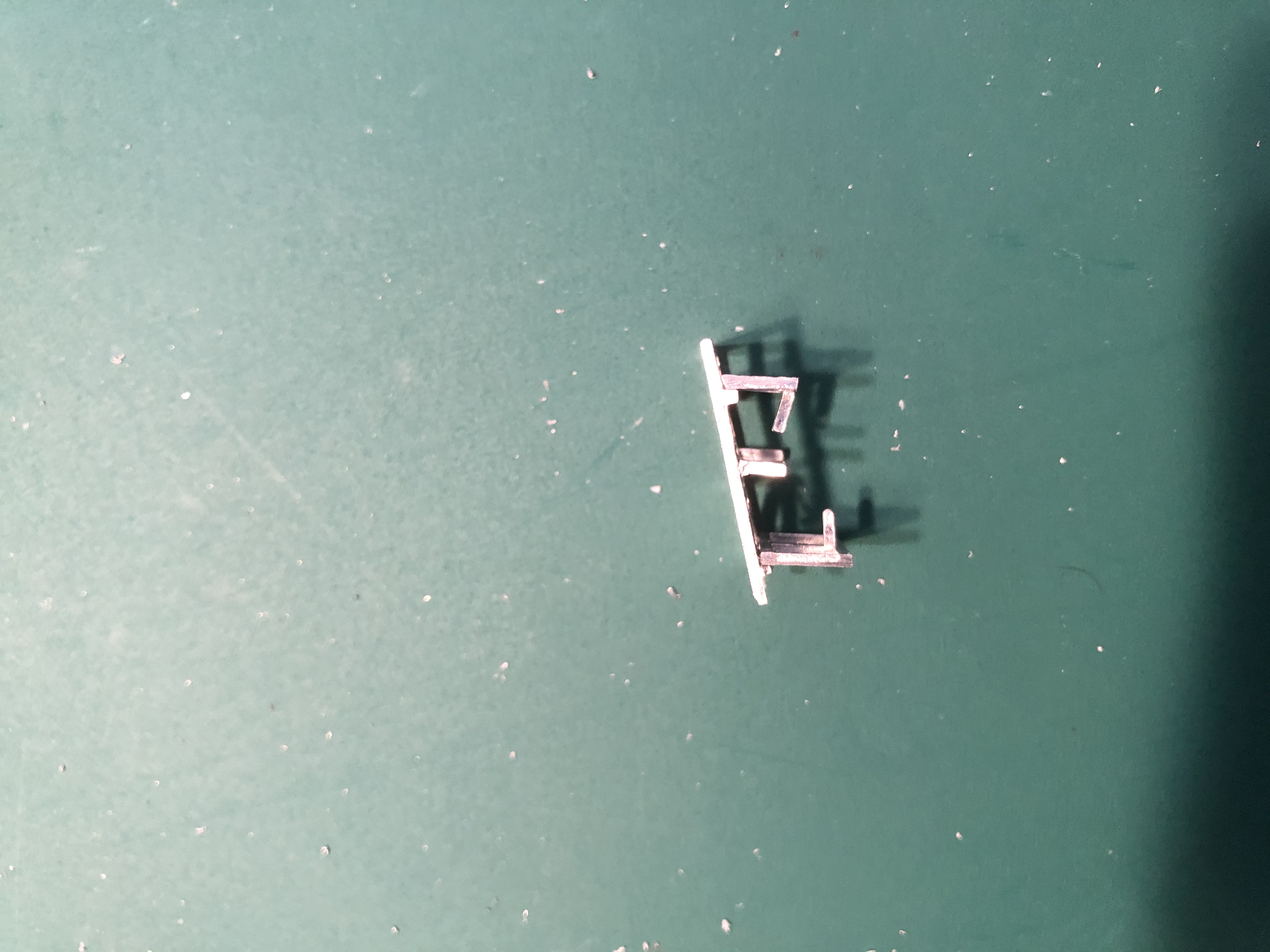 Note the raised rear locating bar on the rear support to ensure it sits down on the hull correctly (also note to me to not use portrait photos as they always flip to landscape and look bonk on the post!)