


![O-12 Infinity Fast Response! Firebat Attack Wing Unboxing & Review [7 Days Early Access]](https://images.beastsofwar.com/2026/01/unboxing-corvus-belli-infinity-firebat-attack-wing-coverimage-225-127.jpg)


Infinity Terrain


Recommendations: 942
About the Project
designing, Building and painting Infinity terrain, plain and not so simple...
Related Game: Infinity
Related Company: Corvus Belli
Related Genre: Science Fiction
This Project is Completed
Barrels
No sci-fi setting would be complete without barrels. They have been a staple for years but sadly I only own 1 GW barrel. It’s some of the objects that money does not come out of my wallet for but I have always wanted them.
I decided to try and make a more sci-fi barrel. I don’t think it’s all there yet I may come back to this but there is not much you can do with a barrel unless you are prepared to change the shape to not a barrel.
I done some sketches and just used the tools to make some shapes on the software. The only design part I wanted, in case I wished to use these or embellish them further. I wanted a way to link the barrels via hoses this could be to mix and output the contents. This was fitted with 0.9 mm holes the same as the gas cylinder so I can use the solid core ethernet cable wires I have to fit in to pretend there are hoses I may also make connector sections for this to really ramp up the detail. I don’t know why I went with 3 possibly one for beet one for gas, connected to a mixing barrel and a tap for a sci-fi beer scene!
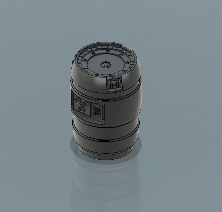 3d Design of the barrel
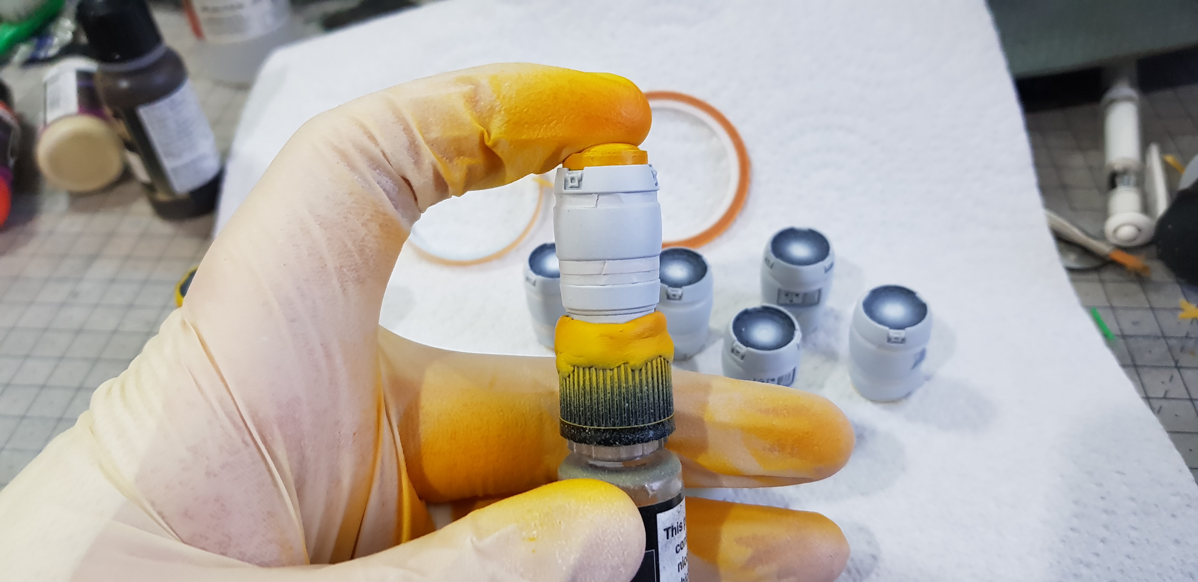 I primed black and done a grey highlight then masked off the lower sections of the barrel. I used a lid to mount this onto with blue tack and a laser cut plug for the top to mask. Undercoated in grey then sprayed yellow/green.
 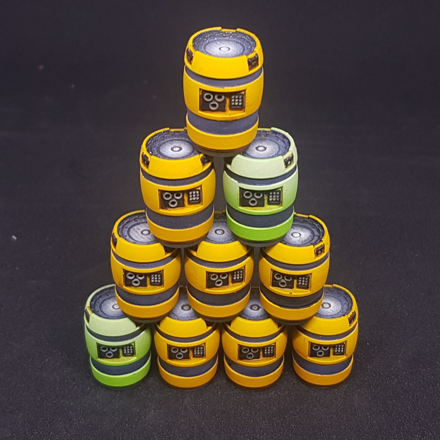 Unmasked and handpainted details then washed (not very happy with the wash but meh!) Done, finished Barrels!
So there I have it. Finished barrels to join the ranks of my terrain. The bottle mounting system made this very quick to paint just spinning the lid meant I could paint without stopping due to constant movement.
Very quick project this was done today. Quite happy with this but there may be another barrel resign in the future as I learn more I may revisit this.
Next will be the roadblock but this may be next weekend or a during the week project. I have made these but they need painting and is the first time I have used Laser and resign prints together (even though this is very simple in this case).
More to come!
Progress on Boxes and road blocks
So what have I been up to? Painting boxes mostly badly but still painting. I refuse to have a pile of unpainted grey plastic especially as I can print some. But I am in the planning stage at the moment. By this I mean I have hit a creative road block of my own. I have a big project planned ticking a lot of the boxes bellow. I cant seem to finalise the design of anything. Everything I do is re-done or scrapped.
So I painted. And Painted, oh and painted.
I have now found a new problem. More detail = more painting.
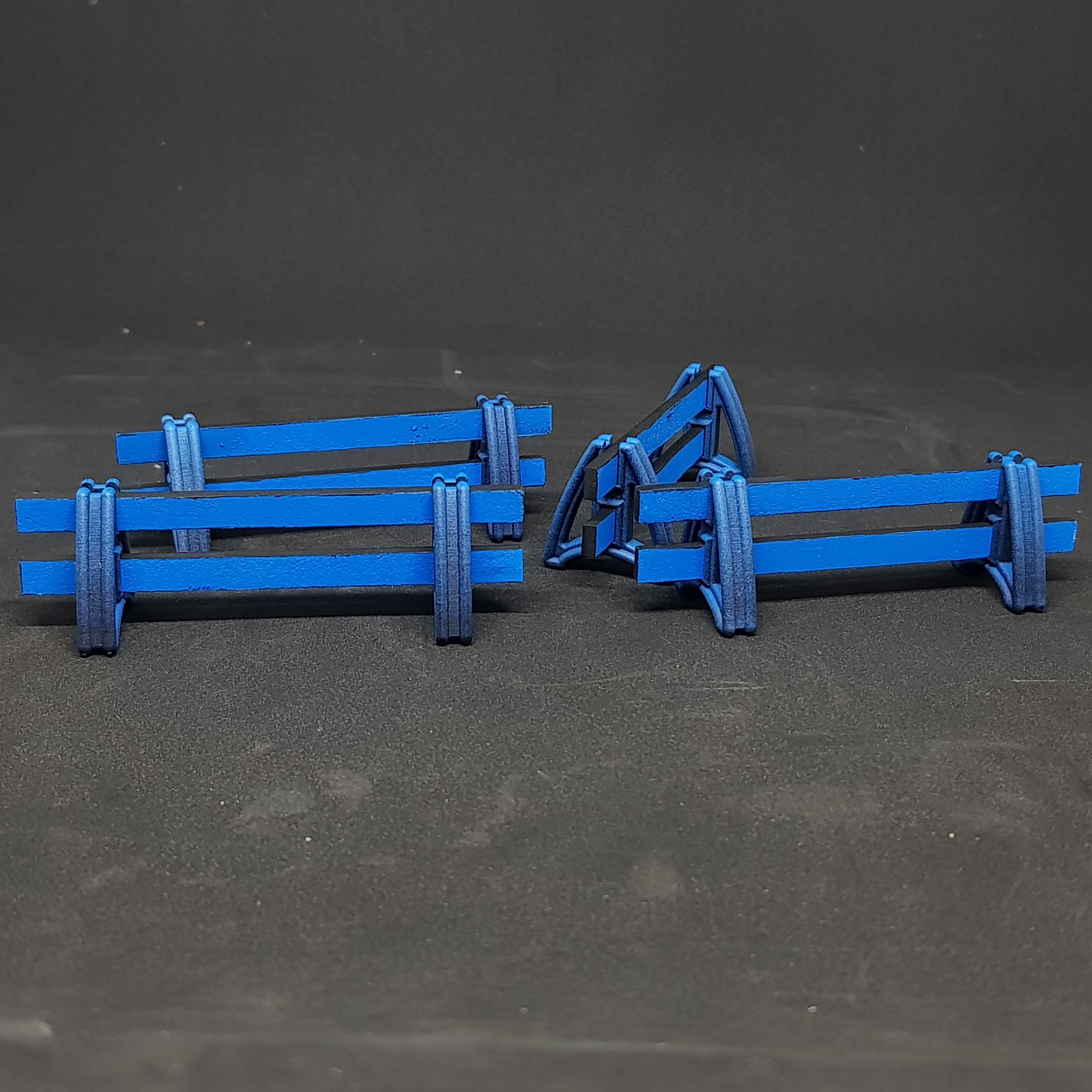 Road blocks done. Happy with the design but not the asthetics but dont know how else to do them. I also think they need some text on them.
 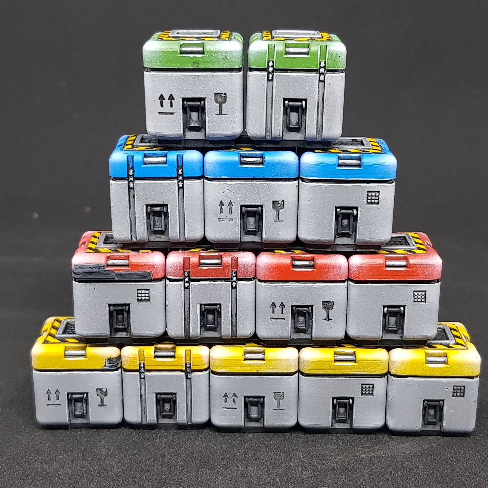 The tower of pain. lots of 20mm boxes. I think I am going to do a simpler design and different shape for veriety. I also included some mis prints but you cant see too much.
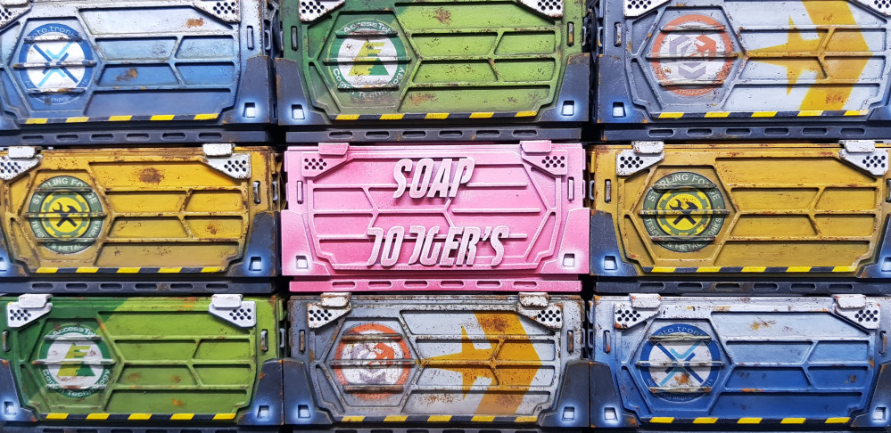
 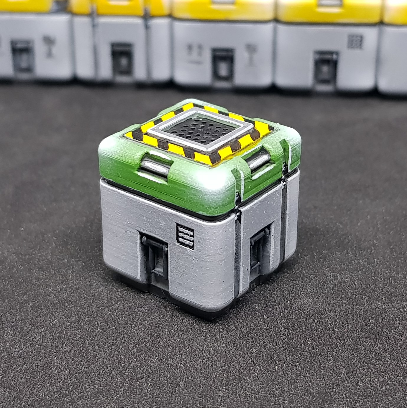 Close up of Box
 Other side of Box
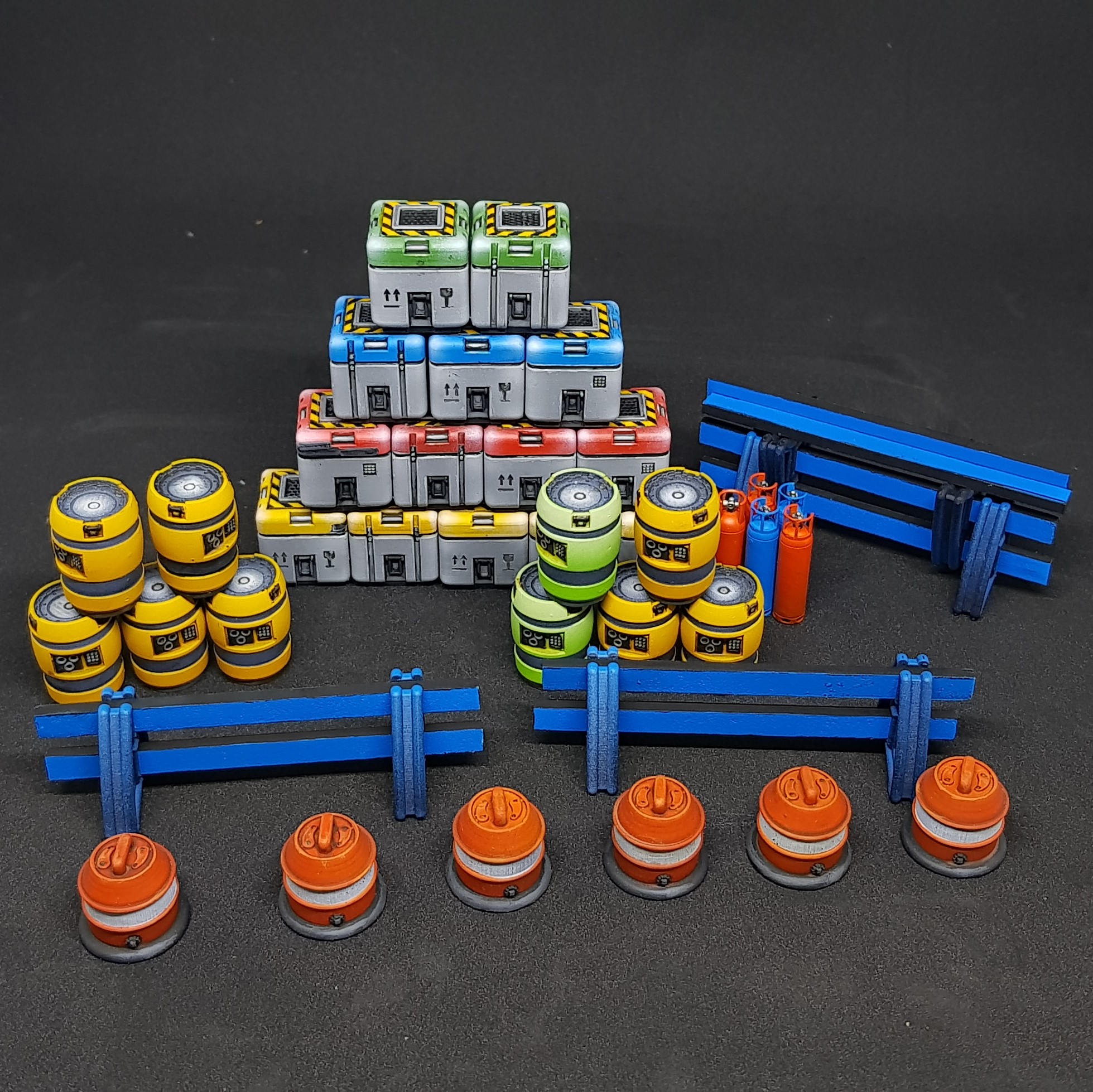 Everything so far.
So far so good. Learning lots and more design needed. I don’t want to talk to much about the big project but it will be the Landing pad but with an aircraft, vehicle and lots of window dressing. It will be in a different style from the rest of the buildings due to this being the first building on the site to help build the rest.
I had a moment of clarity last night before I went to sleep and the design was perfect. I was happy with everything I thought of and it was going to be great. This morning I cant remember any of the details. Morel of the story? Don’t sleep.
More to come but I may step into a fuller project rather than scatter terrain fully combining laser, hand and 3d printing. That’s the goal anyway.
Back to the drawing board
So I am back at the drawing stage of a large model. Quite enjoying this one I have laser cutting in mind along with 3d printing and some hand skills as well.
The next project within a project is my landing pad I wanted to do. Always want one of these but never liked how they have been done. The standard is a circle or octagon on stilts.
I like stilts but why would you have them unless you were trying to protect the ground, surly this makes it harder to load cargo and it makes much more sense to have it on the ground…
Unless you have some sort of cargo system to load of offload cargo, this got my ideas flowing. So I decided to start to build my landing pad and have taken far to long and have 1000 components already to start to print and cut. I think I am going to start to print some components soon.
So far I have designed a column 😀 this has taken ages because it pretty much works. All the components have ball joins and material tolerances so they fit together when printed. The robot arms can move up and down etc. I wanted this for possibility. I also have numerous ports on the parts for power and cables (added later). This is going to be the well used first landing pad the enabled the rest of the buildings to be put up.
There will be an automated truck, a cargo container (which I done before) being raised up into the cargo slot of a drone flyer, along with some kind of control tower. Quite involved and should be fun.
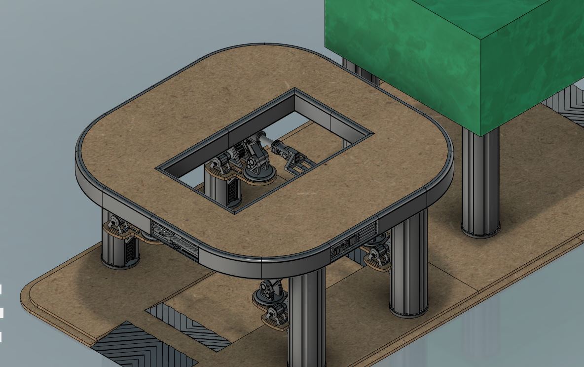
The only point for scale is the white sections. They are sections of plastic lollipop sticks 4mm diameter.
Here is what I have so far.
 Total layout with columns
 Close up of one of the robot arms which are going to be lifting a crate. (hopfully)
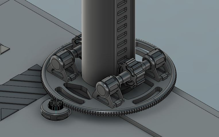 Original design the robot arms didnt need to be each able to 360 around the columns this is partly why it's taking me so long.
 So that’s this so far. Will continue to work and post as I progress. I will be working on the structure holding up the control tower. then will move onto the platform. And possibly start printing the arms and columns.
More to come but possibly just more drawings.
Drawing got dull
So in the past couple of days I couldn’t keep drawing. I enjoy it but I prefer building and painting and I was starting to get a mental block of how things should work or look and the overall feel of the model.
So I decided to start to build it since the first floor was done apart from add on parts.
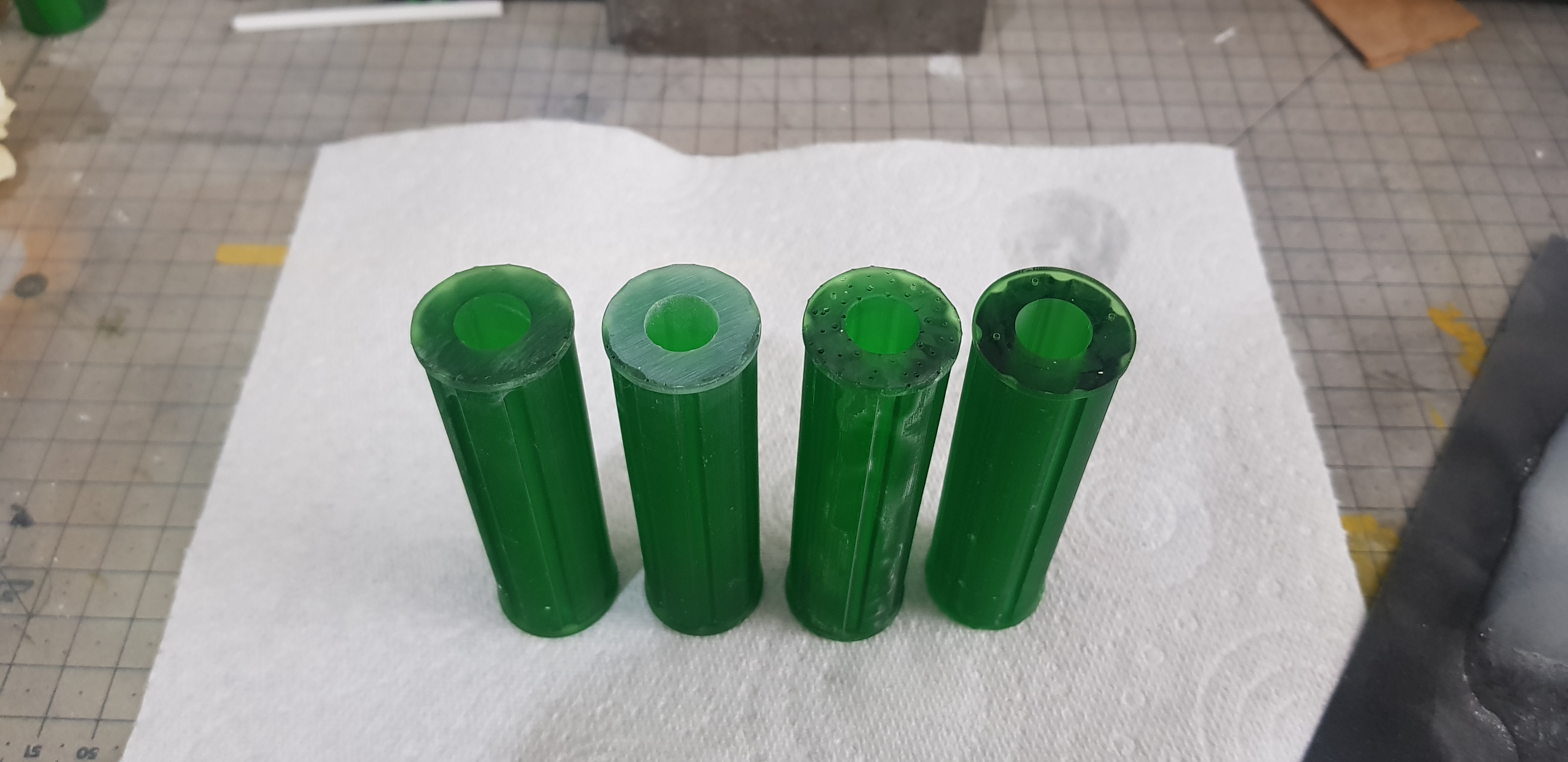
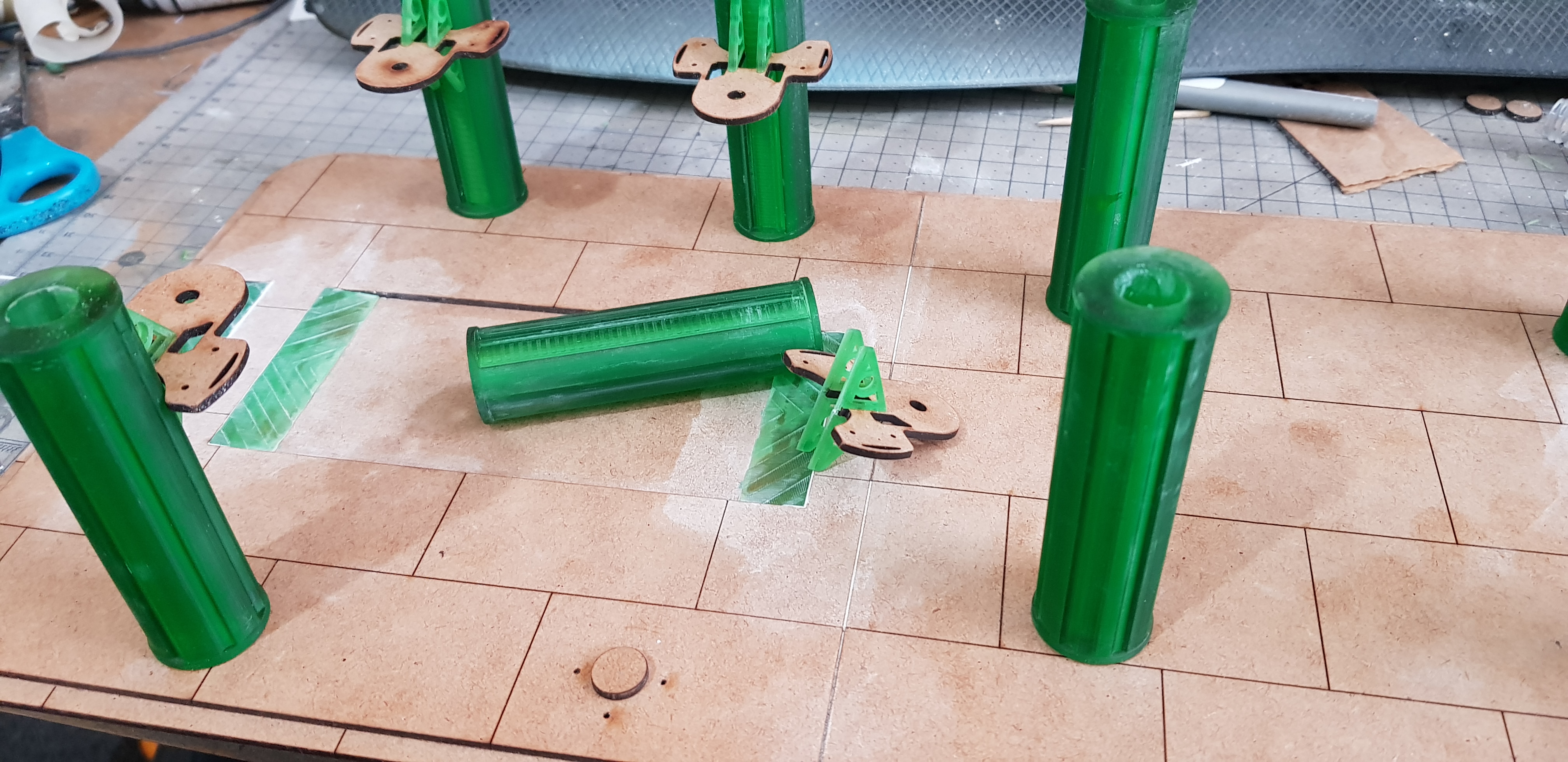
I started to use green clear resin as it’s much faster then the grey. I still have not done the test model on my 3d printer. but the green resin came with it. Spoiler alert I much prefer it to the grey.
I started on the columns I have two types one with a gear inside it and one without. I started with the one with the gear and had my first major print failure. I Went to bed and didn’t top up the resin. Stupid mistake probably a £4 mistake. Not the worst £4 I have wasted but now I have some bits or my bits box. It takes around 7 hours for 4 columns to print this was done overnight so didn’t mater much about the wasted time.
After the prints come out the are covered in goo I split them up while covered in uncured resin place them in a jar of alcohol and put them into my ultrasonic cleaner.
After they come out they are not tacky they are kind of like a hard gum but easily scratched. I remove the supports which on the bottom surface most of the detail is gone and it sort of balloons I then sand this to flat with wet and dry and keep the dust down then do this more until flat enough. The parts closest to the fep the film at the bottom have great detail.
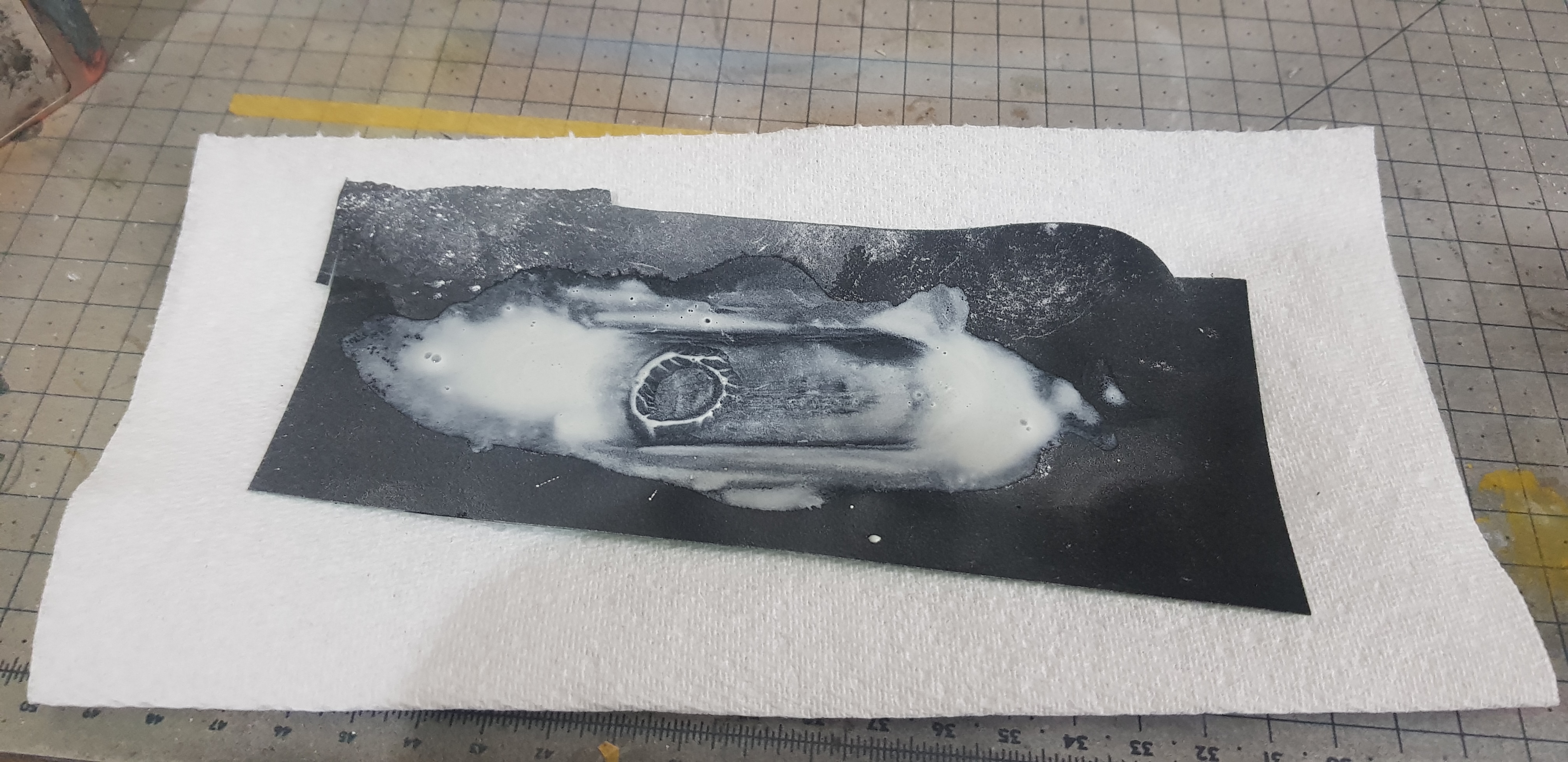
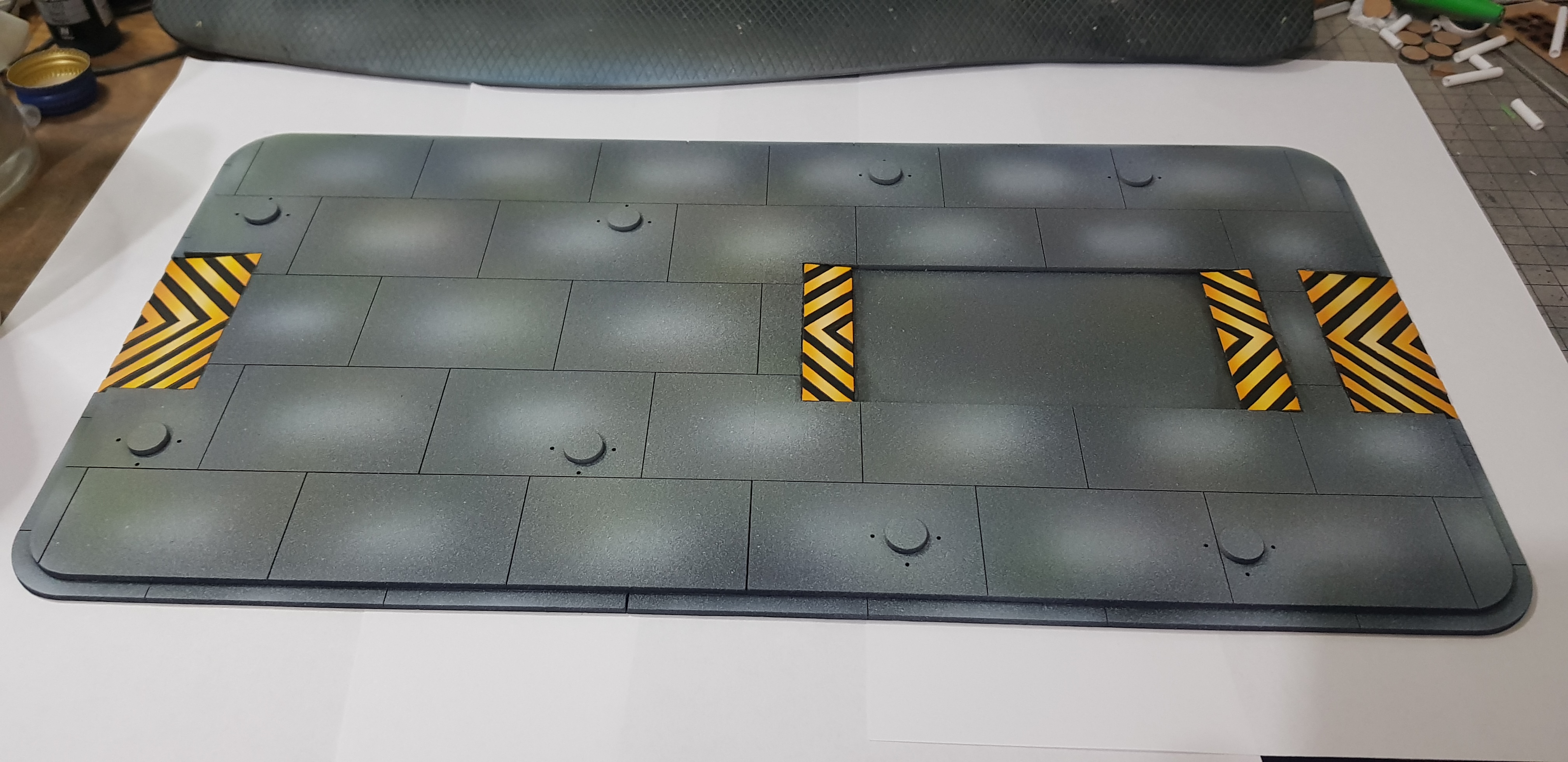
I also went onto laser cutting the base and printed and placed the hazard stripes into the board.
This was done with superglue and then going in with Vallejo plastic putty. I also filled in unwanted lines on the board and glued it together with PVA.
At this stage I also laser cut the lifting platforms and started to print the components to the robot arms.

The robot arms turned out to be a pain but that was a learning pain of using a 3d printer. I know the tolerance of 3d prints is make things 0.2mm bigger but when you also include the end of the bed this can be more and the orientation of the print matters as well and I cant calculate for this built it is consistent but it may take a bigger brain than mine to work this out.
Parts, resin to resin do not line up as they should but 3d print to laser cut do. I think this is because when the laser cut objects which are crazy accurate it is a 0.02 deviation that I can account for but 3d print to 3d print may be 2x 0.2mm accuracy difference which is. regardless I just make it work in the great old modelling style.
Each robot arm has 16 components and 6 axis of movement making them very posable and complex. I made 4 of them and they do work and roll up and down the column with the rack and pinion and the guide rails. This was a tight fit band stayed in place but now with lots of play are a bit loose. they do need cleared more and then fixed in place but they seem to work well.
Don’t know how I am going to paint these but I know it’s going to be basic.
I also base coated the base board in Poundland spray paint black this showed where I filled and where I didn’t which isn’t a great look.
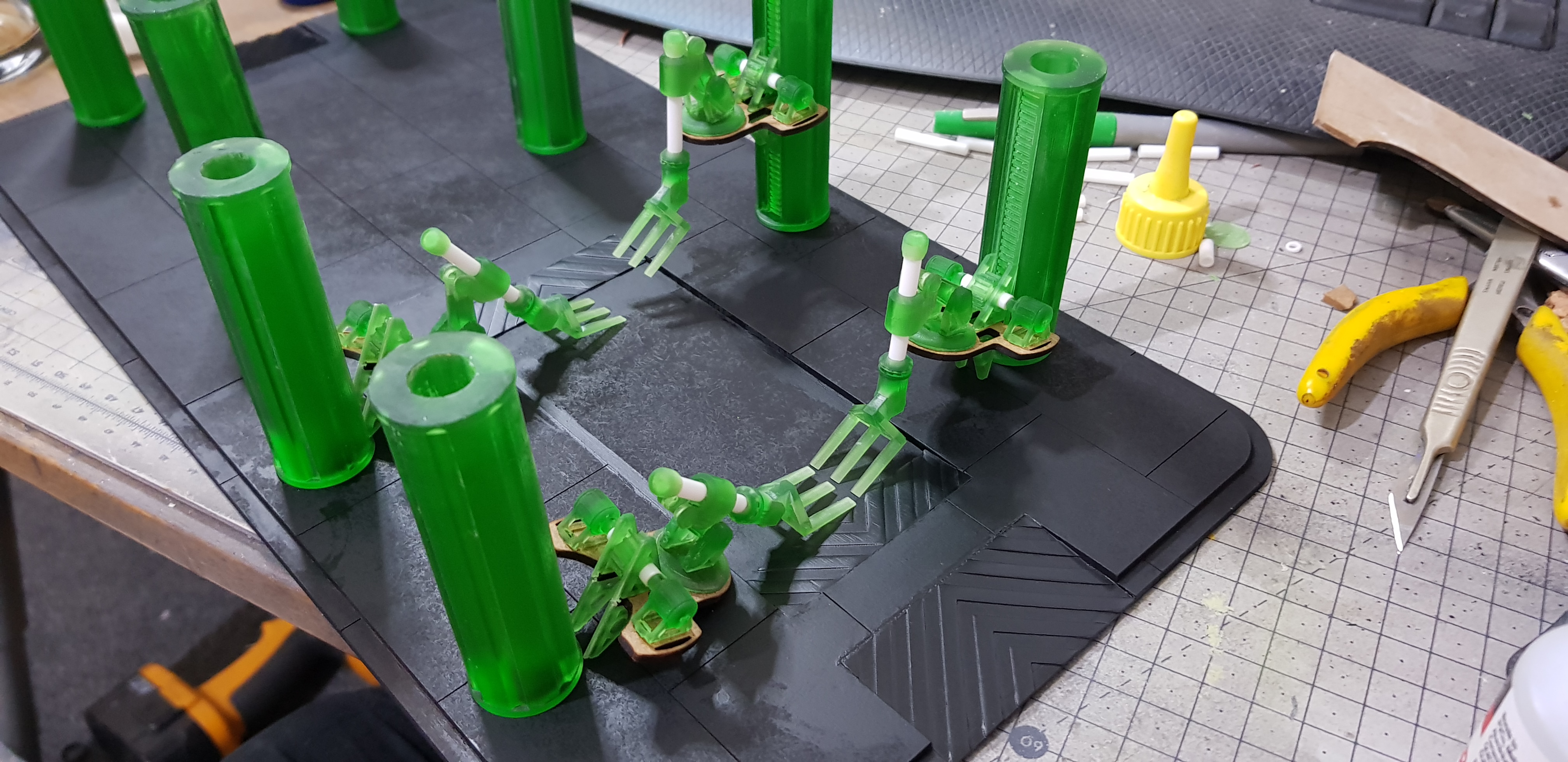 All current printed and laser cut components together for the first time.
 I couldn’t let the finish on the base stop bothering me. I sprayed over a gloss coat (again Poundland) this made it look great but then when I went over again this came through again.
I carried on regardless and airbrushed a light dusting of black then grey then some blue and silver and some green and bone. All Vallejo primers. this looked good to me as a base concreate I will do more to this finish later.
I then masked off the ramps and sprayed white primer down went in with orange at the top and bottom then went in with yellow and then a stripe of white across the middle.
After this as this was 3D I went in and hand painted the stripes in black.
I need to put some text and details onto this like a robot working area warning on the ground.
This will also have a lot of clutter placed on it creates and pipe coils and spare parts. and a autonomous vehicle getting a container placed onto it by the robotic arm. Should provide a lot of cover through it . there is also a staircase to go in for the other building but I have not designed that yet.
 Building base in it's current state.
 I still have my drawing open and am working on the landing pad at the moment. This is supposed to look a little on the used side but not total disrepair. This is one of the first buildings on the site and part from flat materials all comments will fit into a container.
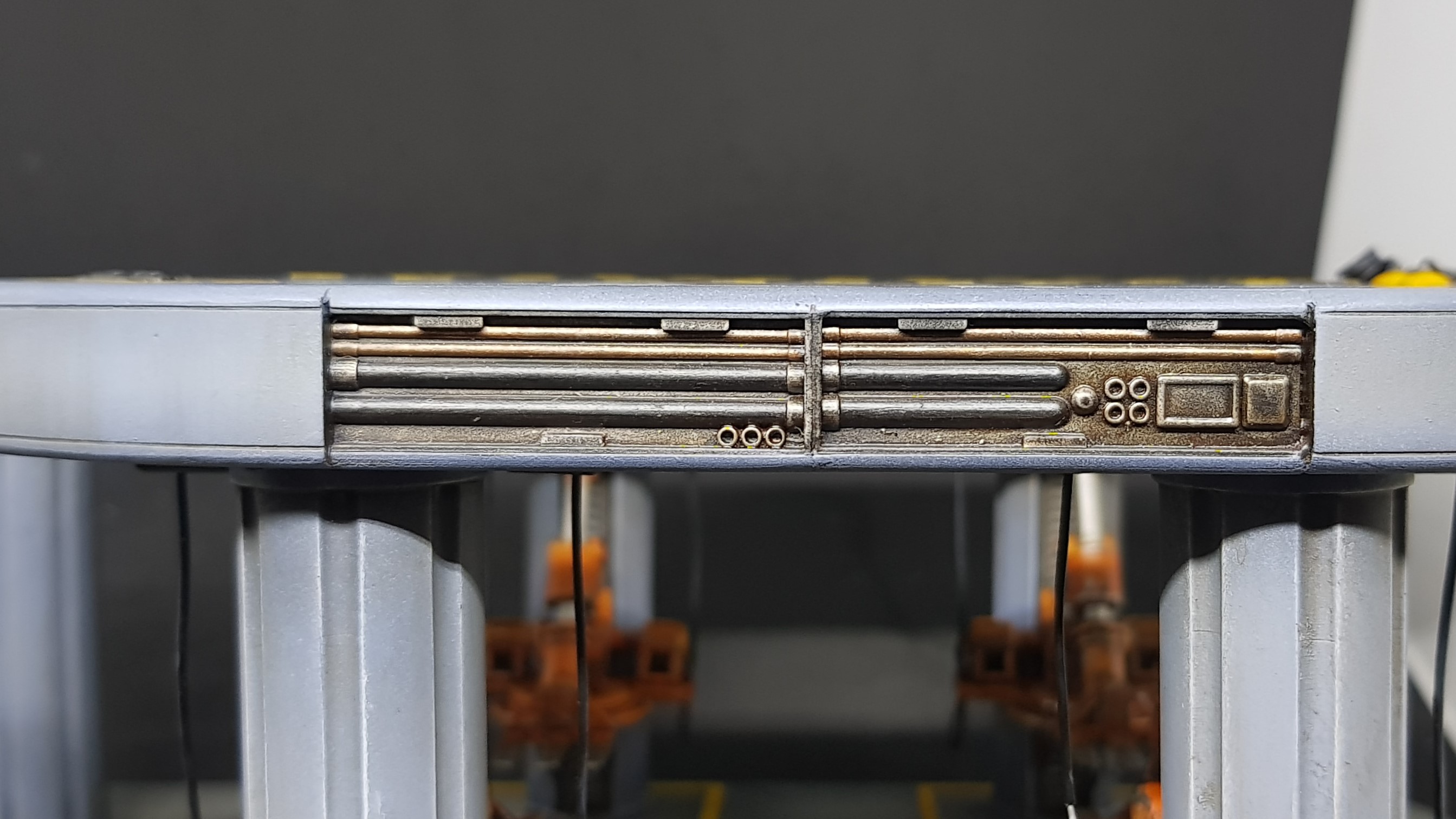
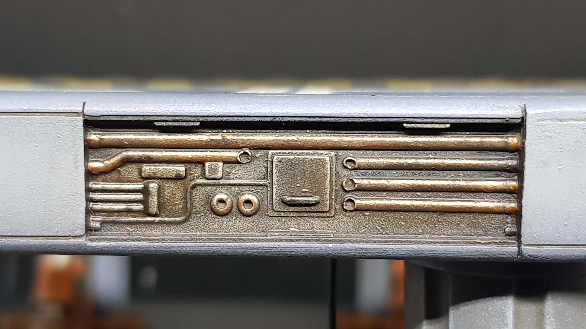
Some panels are missing and there will be hanging cables in places. plugged into ports on the exposed side panels. The big green building is the control/coms tower which I have not finished the design and this will also somehow link to the landing pad. I am liking linking MDF laser cut to 3d printed parts. I am learning a lot and may have to go add tolerances to all parts or I may just cut and sand them.
 Current drawing
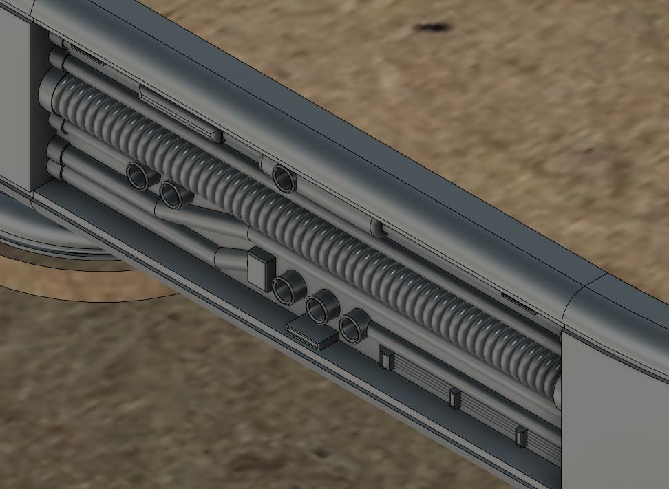 Side detail
So that’s me so far. Still got a lot to do. A frankly daunting part. I am still excited to get a landing pad that I think would work in real life with an actual reason to be on a platform.
More to come. Hopefully soon.
Next more painting, assembly and drawing. Keep making awesome projects, I place more likes than comments due to time but I still love seeing everyone’s work! Glad I am not the only crazy one.
1st floor almost fleshed out.
I continued my progress on the first floor. At this point I have a stair case that needs to be designed and built but this is pretty much it without scatter terrain on the model (which there will be a lot of.
 I started by using my laser cutter to cut out stencils I cut this out of thin card and stuck them down on the model with masking fluid. This works great and I got very little bleeding. I also got some blue masking tape to try and oh my god I prefer this stuff to normal masking tape and it's also lower tack so no need to scrape over my trousers to take the tack off of it.
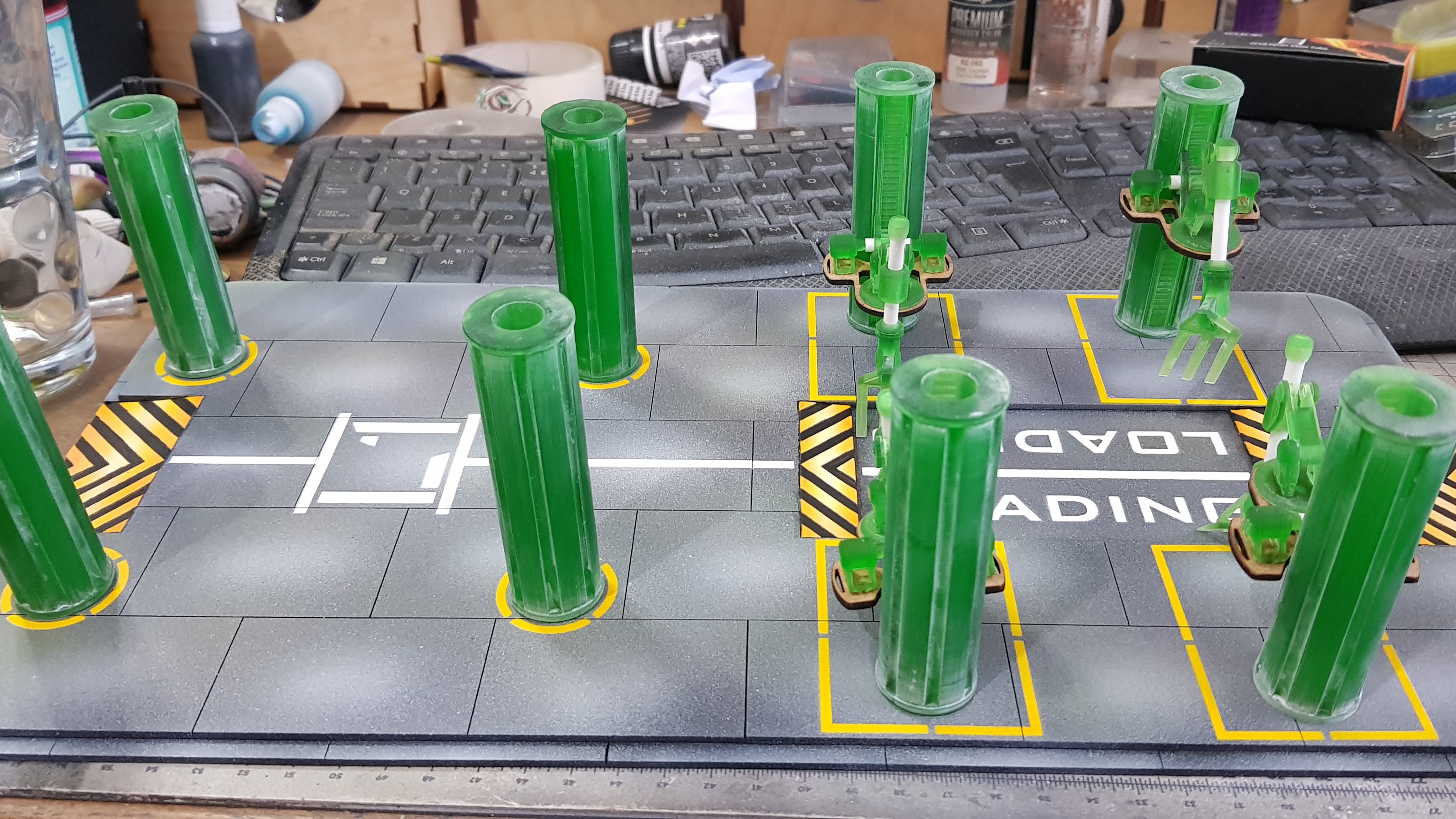 I done some more sanding which was just a quick pass over everything. This leaves a white hard to remove in places powder but it didn't seem to matter to the end finish.
 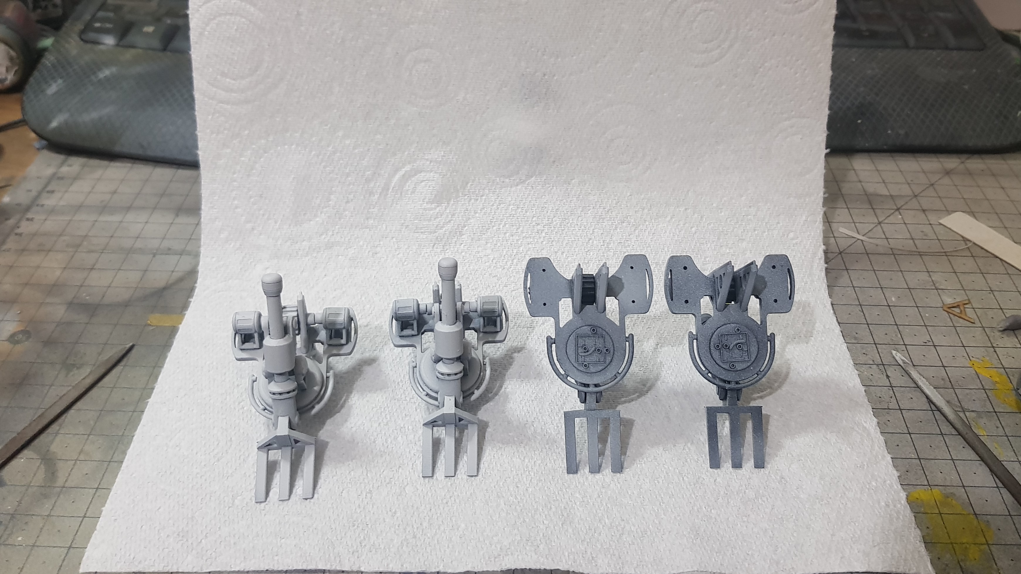 I primed the robot lifting arms and this brought everything together. I painted these orange in the end but I didn't want to pick out every detail but I used enamel pin wash and sponge and paint to weather them. The rest will be further distressed but only after everything is together. I thought this would be difficult after assembly on the arms.
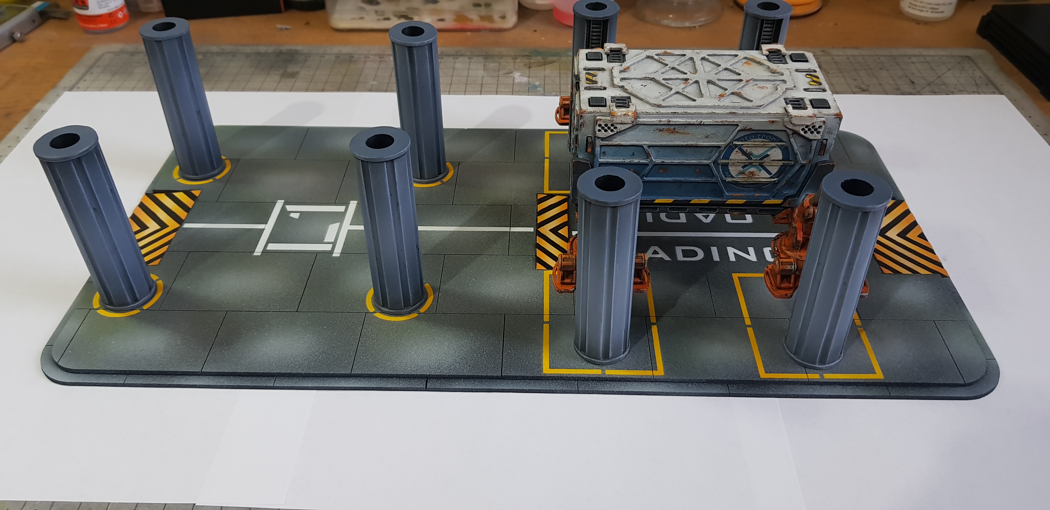 So that's everything almost complete for the first floor. I need to start to draw again. I hoped to do this side by side with building but I was enjoying it to much to stop.
 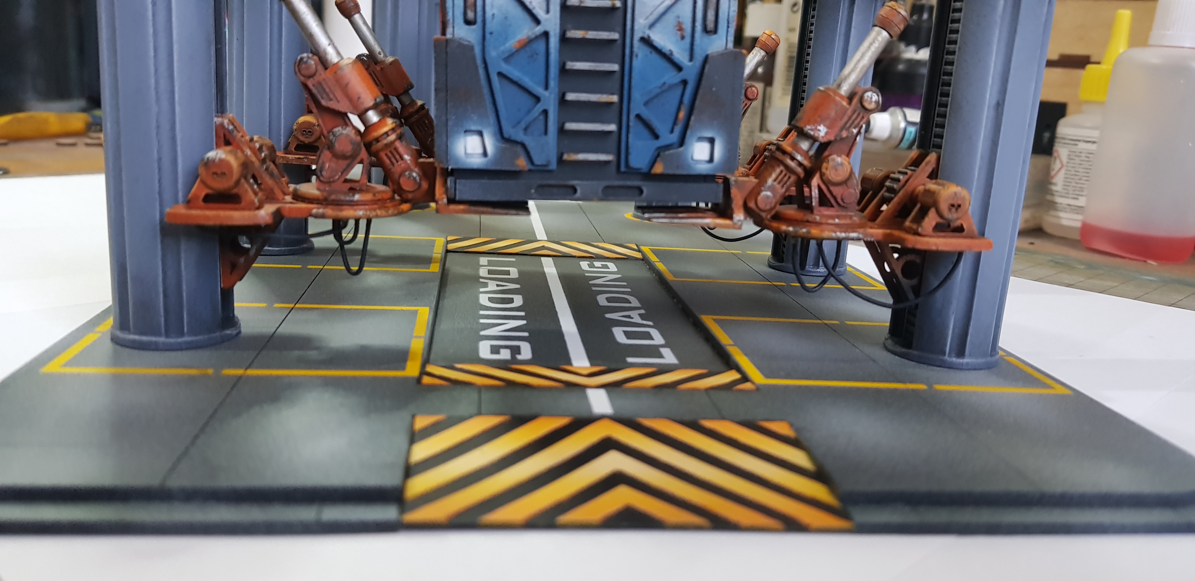 detail picture showing this from the front the container is not stuck down and pushed fully into position.
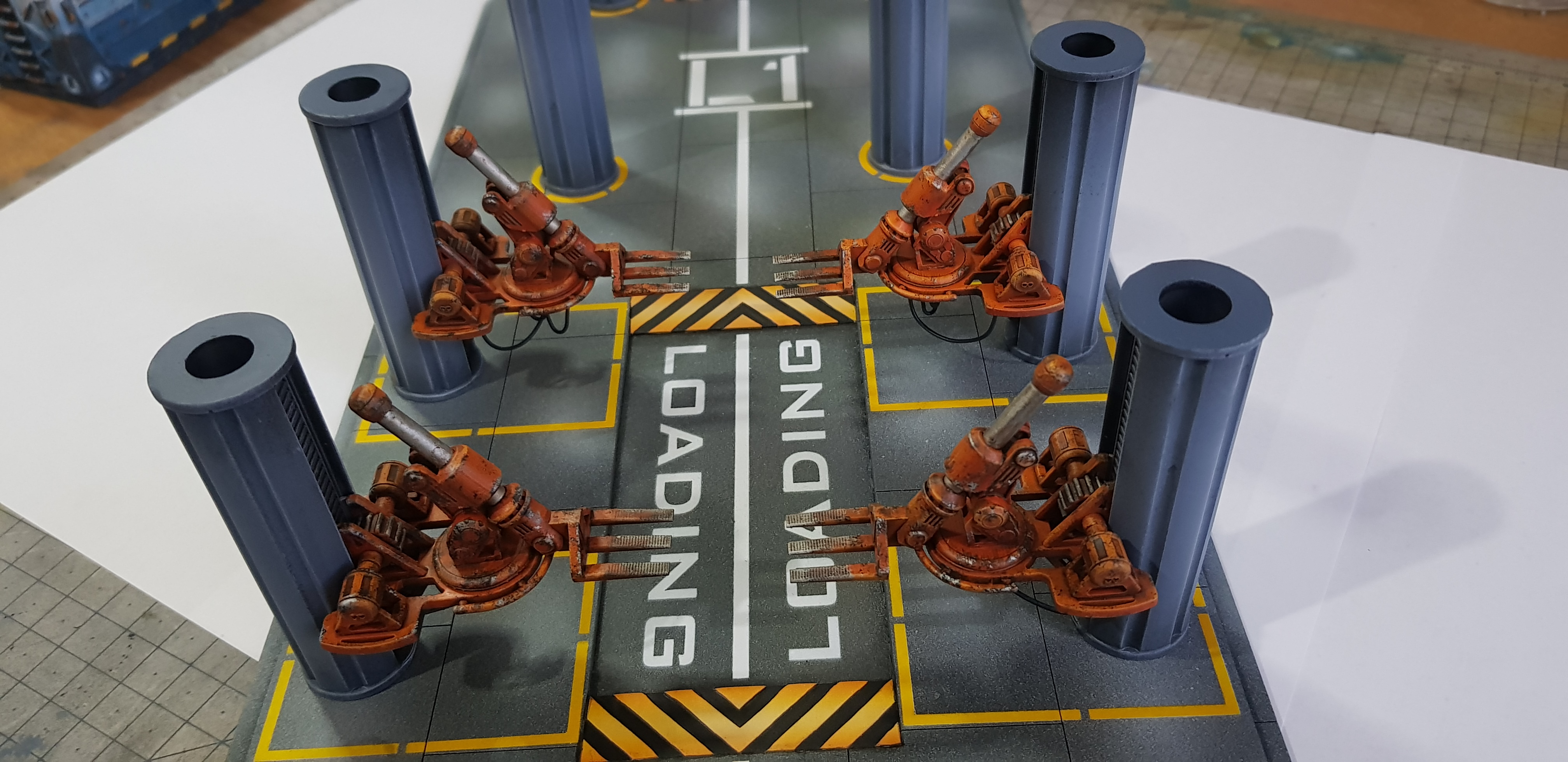 One of the robot arms without anything in the way.
 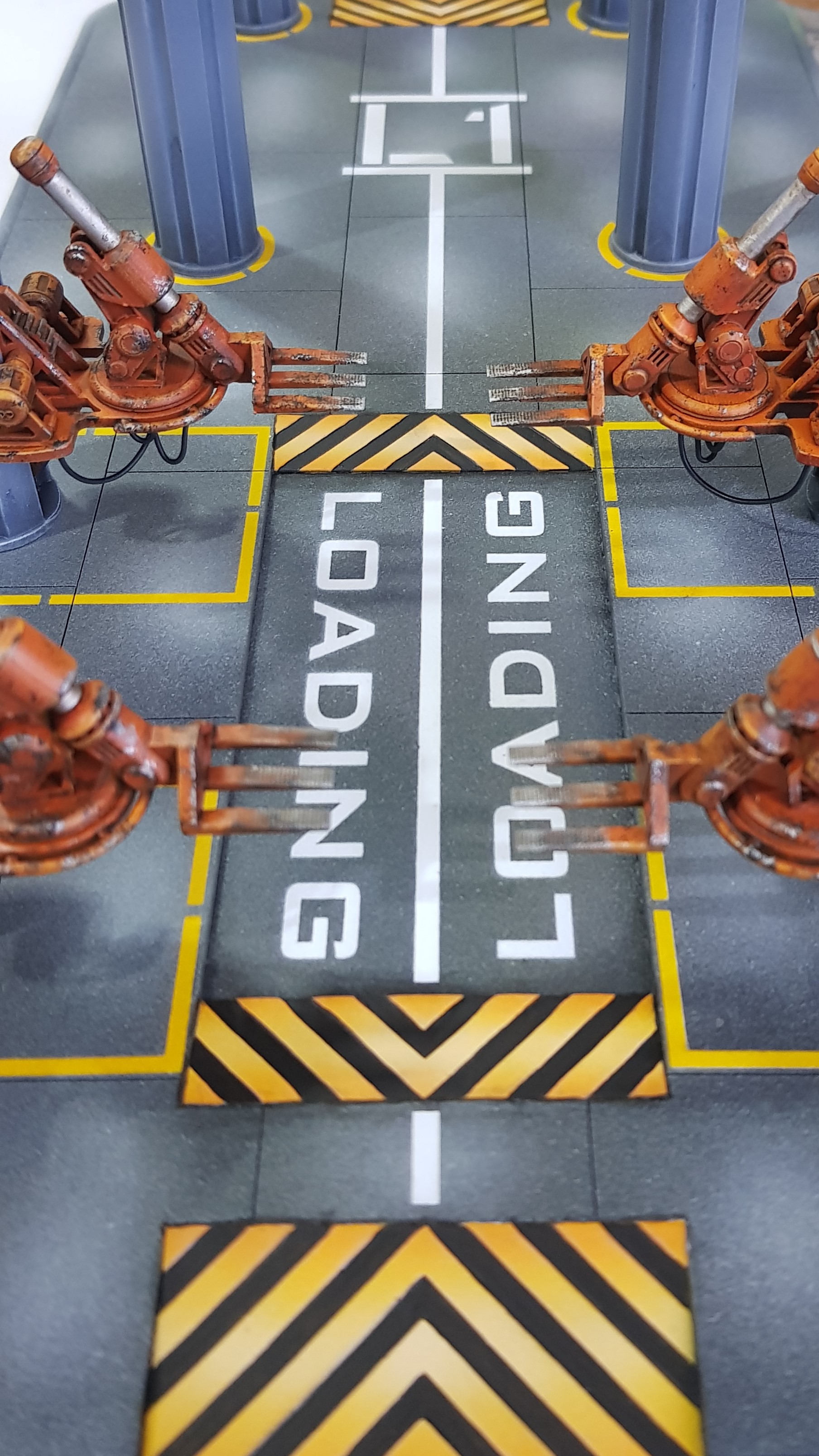 Another detail shot of showing the stencil work.
 I do have more cables to be suspended from the landing platform and feed the robot arms and the motors. This is getting to the point where I am happy with the progress. Cant wait to finish this but I am enjoying the progress so much I don’t think I want to finish.
More to come.
Landin pad, a new sanding game by soap dodger.
So I have been sanding… I mean building the landing pad. This was last weekend and this weekend. Turns out making lots of 3d printed and laser cut parts means Sanding if you don’t truly understand the chemistry and tolerances involved. It actually wasn’t that bad a result but it was uneven around the rim where the 3d printed parts met the laser cut.
This was further exacerbated by me printing directly on the printed without supports. meaning the flat sections are a little smaller than the curved which were printed with supports.
I didn’t take any pictures of the unpainted platform which is my bad. to be honest I didn’t see this as a stage I assembled everything by gluing it with superglue into slots. I filled in around the run and got to the point I couldn’t see what needed filling again. So I primed the platform and this also acted as a fine filler and filled again on top again sanding down each layer until I couldn’t be bothered anymore and started to paint.
A tip if I could give any would be to take your time sanding especially if you are using Vallejo plastic putty if you go to fast it tends to bead and roll up under the sand paper and rip it out from deeper sections.
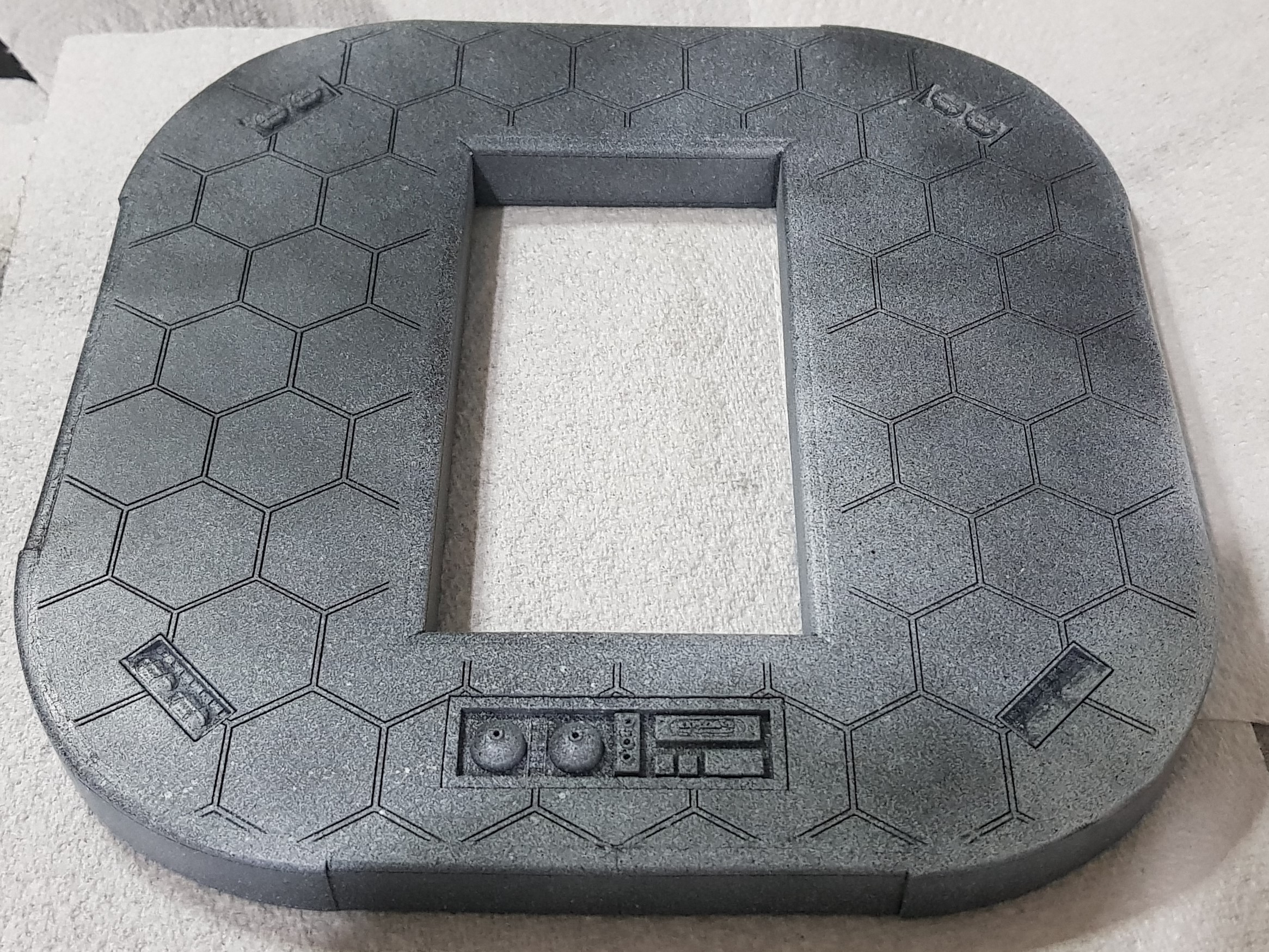 Platform assembled and first fill pass and primed as a filler as well using Poundland spray.
 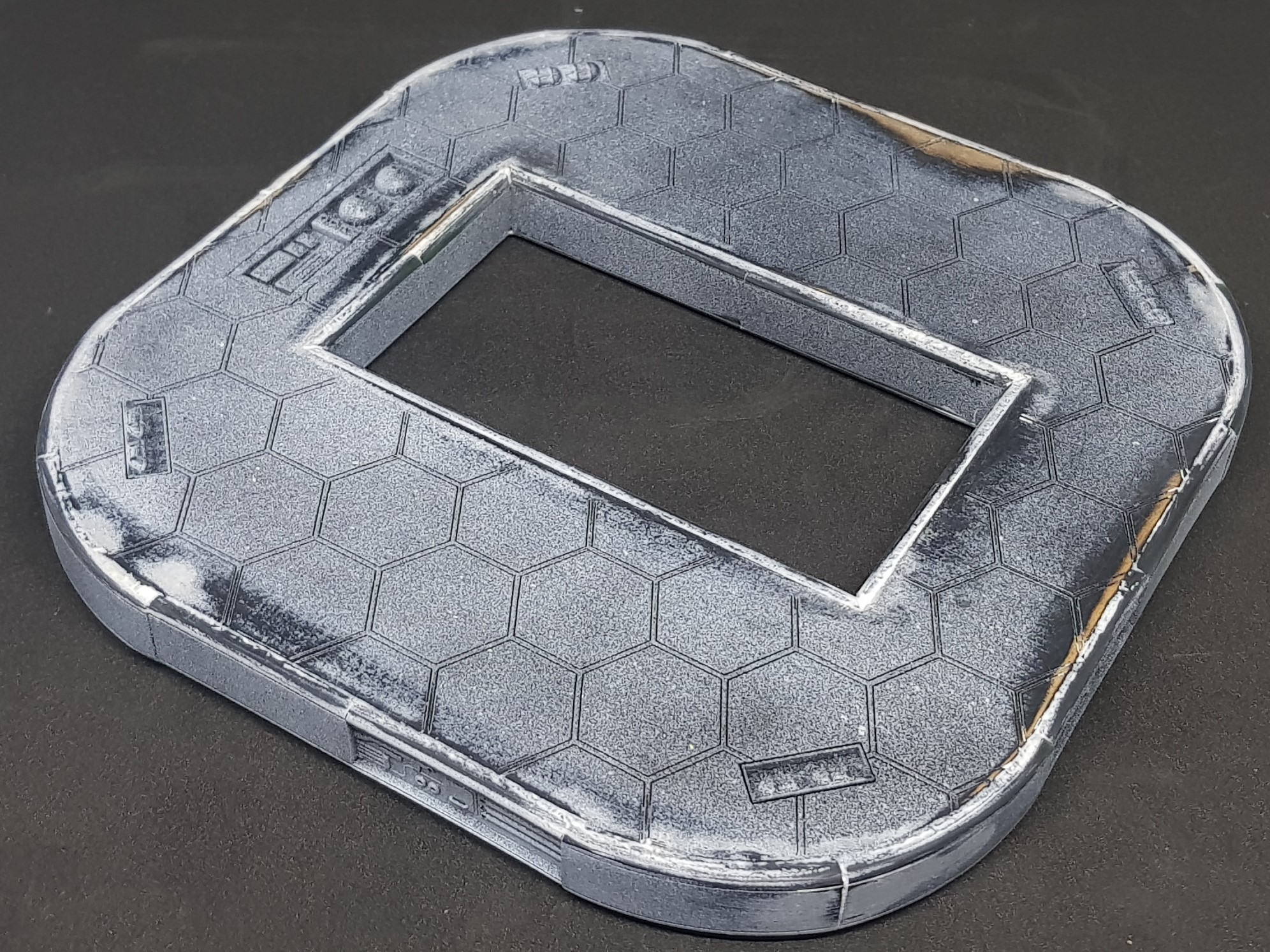 More sanding and this was the second fill pass. I gave up at this point it could have done with one more.
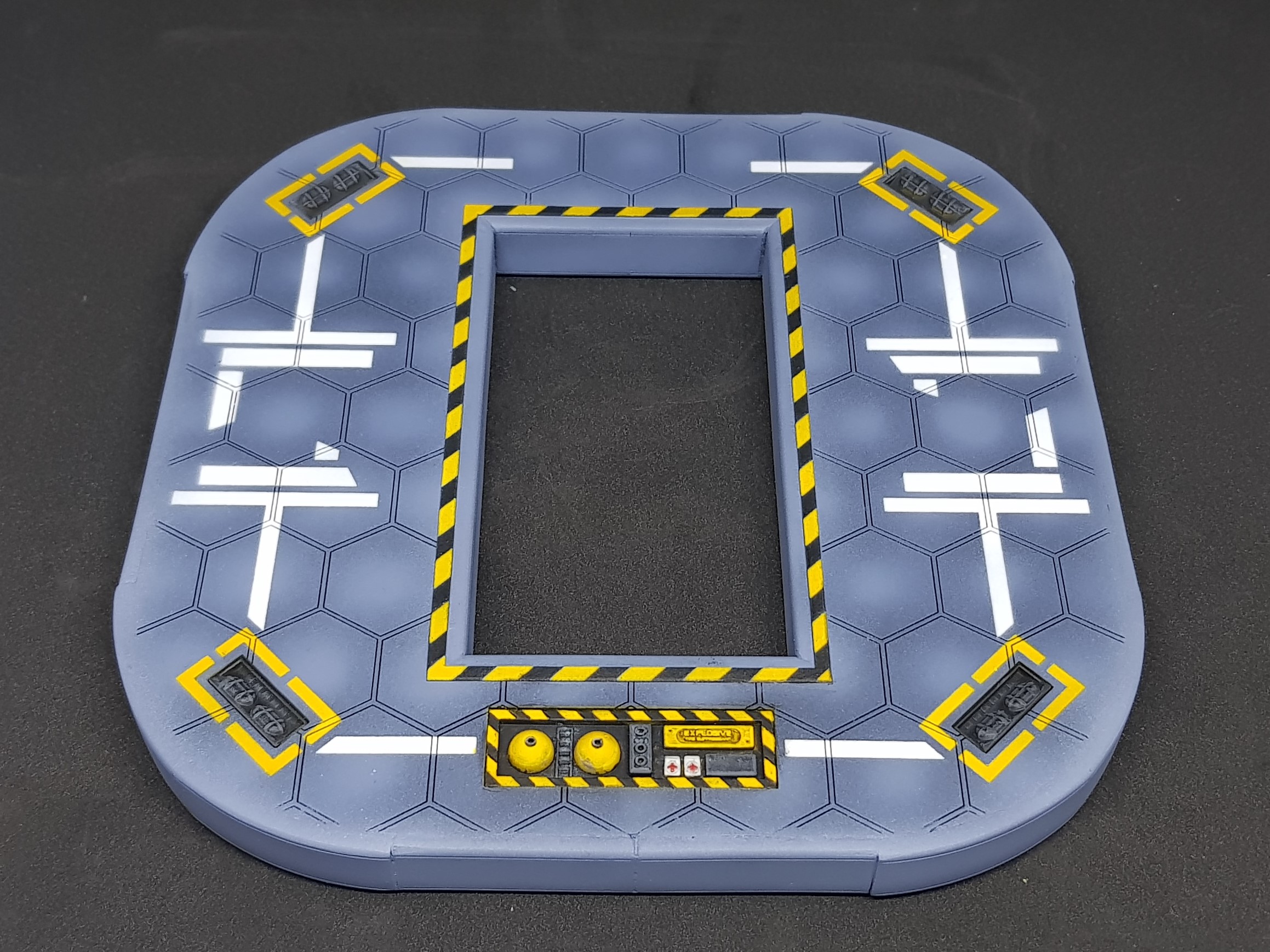
  Basic finish done after undercoating with airbrush primer and grey.
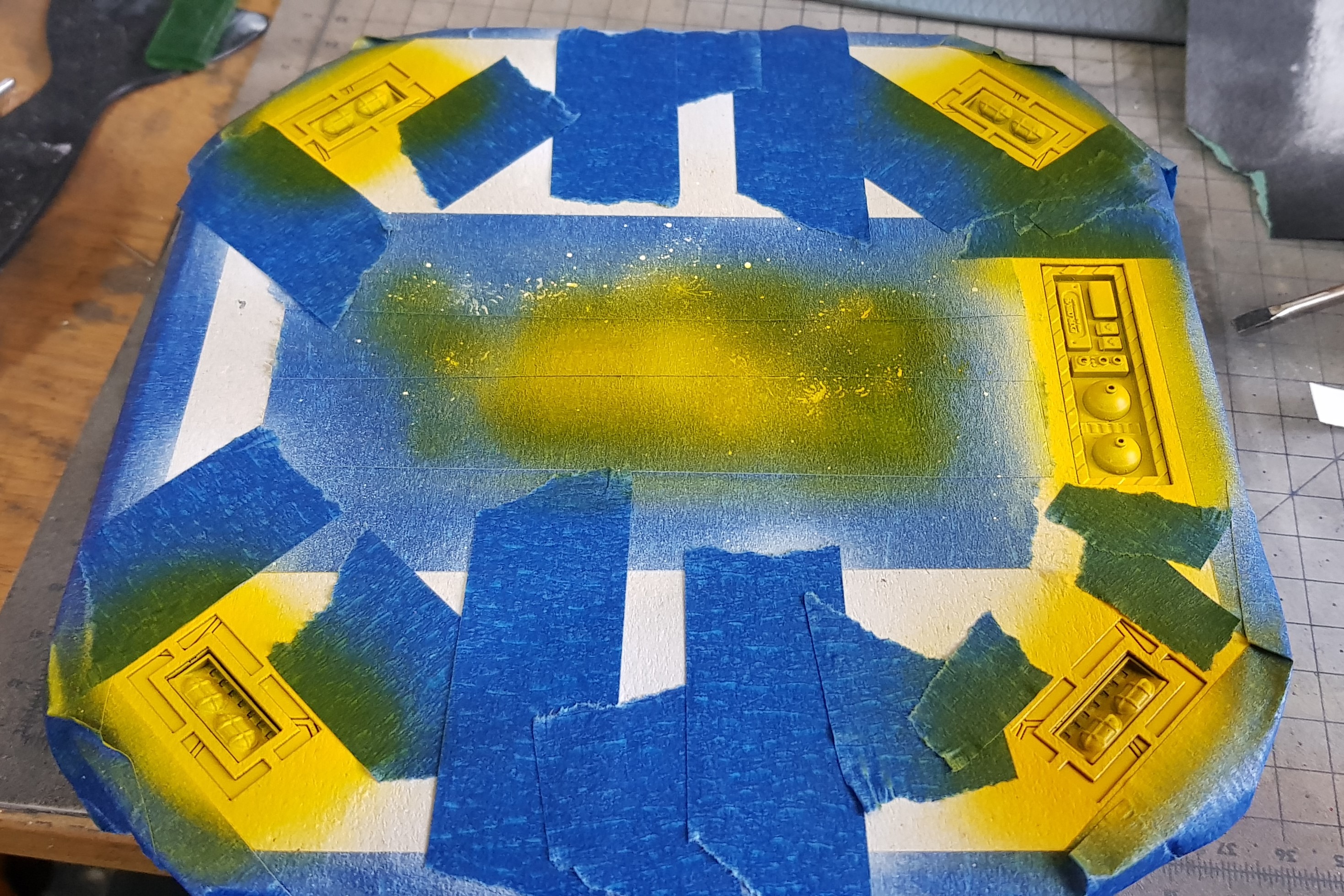
I turned my attention to the hazard lines around the loading opening. I tried 3 times to 3d print these. It didn’t go well. I tried unsupported each time and my bed while level enough to print off of is not level enough to print something so thin and flat.
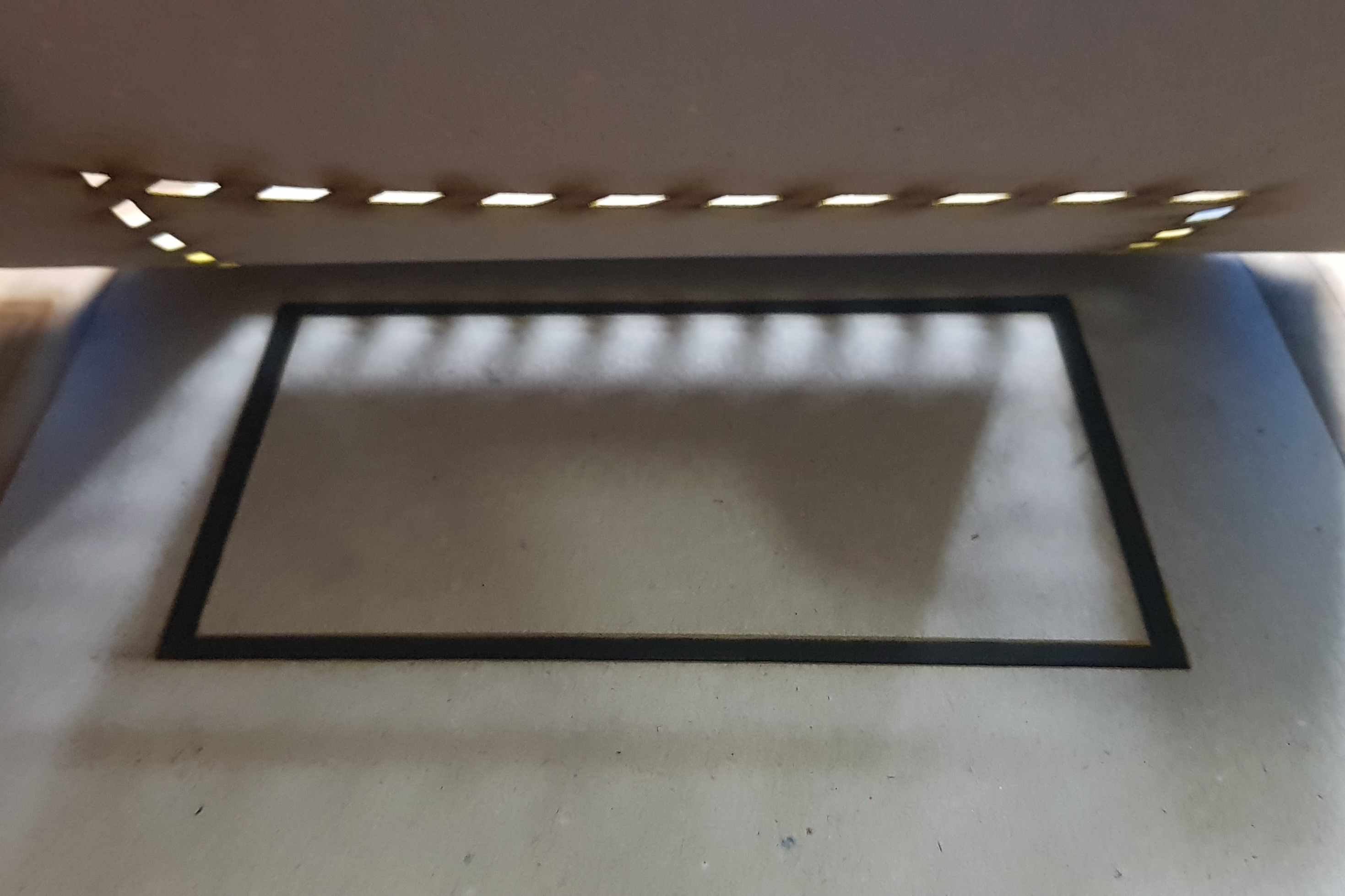
I turned back to the laser cutter. I am known for spending hours on hazard lines but I honestly couldn’t face anymore (for the moment). First plan was to make 3D ones. This would have used up most of my hobby time but would have looked cool.
I cut out a jig of sorts as I wanted two one for the bottom and one for the top. This was two pieces of card. One with the hole for the base of the hazard stripes and another for the yellow sections. these were half stuck with double sided tape. I then primed the two rectangles and slotted them into the jog and sprayed grey then yellow while holding the template down.
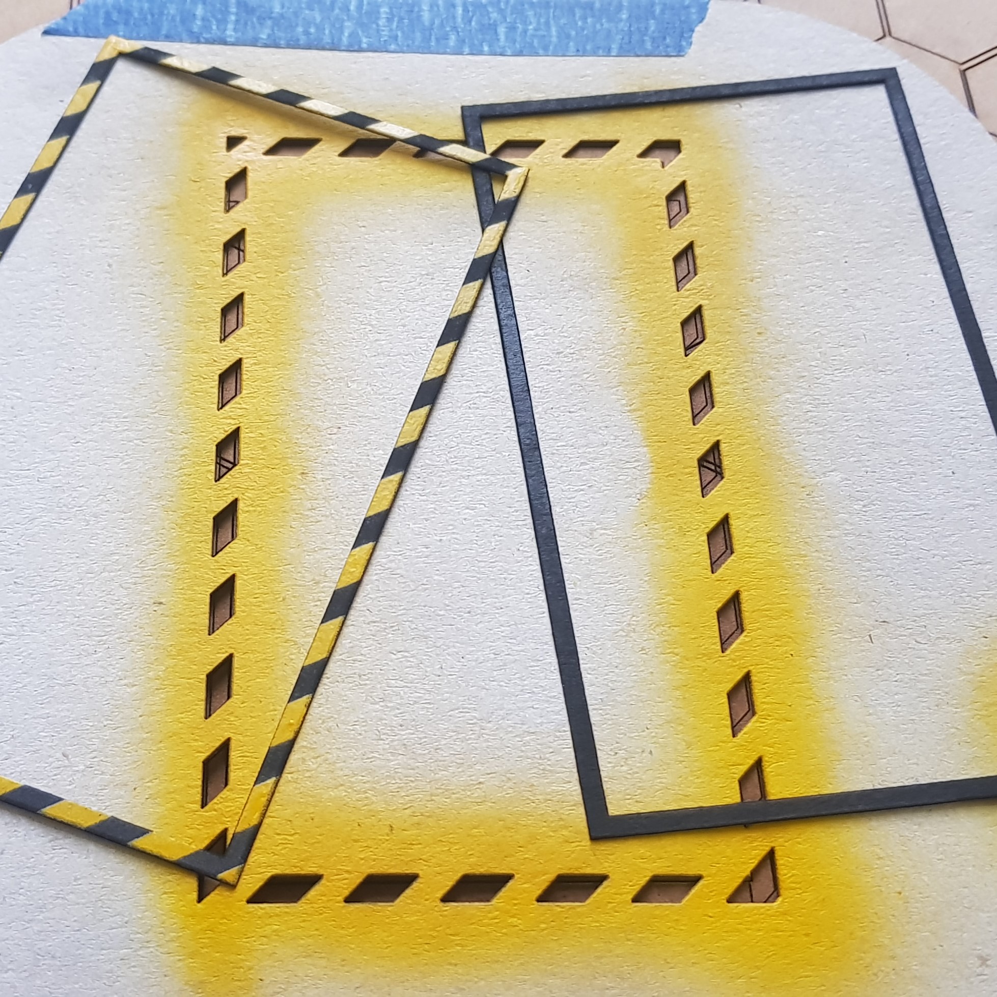
The next step was to start to fully paint the planform. I wanted to use more stencils so decided to keep it as flat as I could and didn’t glue down the hazard lines.
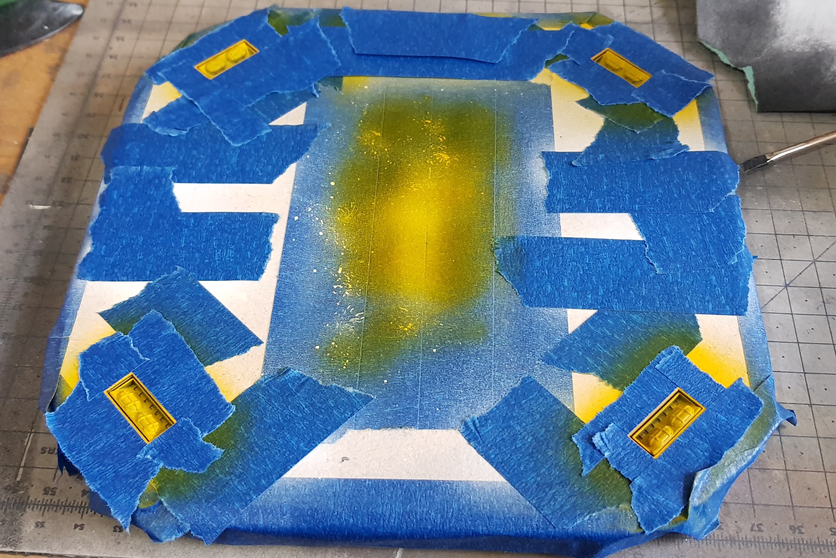
I wanted this to be quick. I cut out my mask. I used liquid mask to stick it down on the platform which is my favourite technique. I also wanted multiple colours but only one mask.
I prayed white then masked off the white over the stencil and the follow and again masked over than then went in with black.
The whole idea of this was to add colour and from a functional point of view give something for the automated drone to lock onto to land.
After this some hand painting was required to paint the emergency kit. I am very please the explosive text came out on the large box. This is an explosive foam that would envelope the landing pad in the event of a failure. along with first aid and a manual fulling station/ spares box.
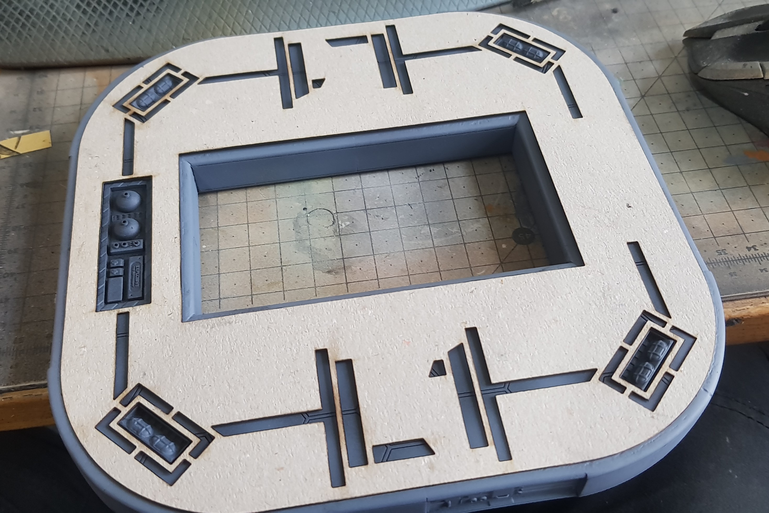
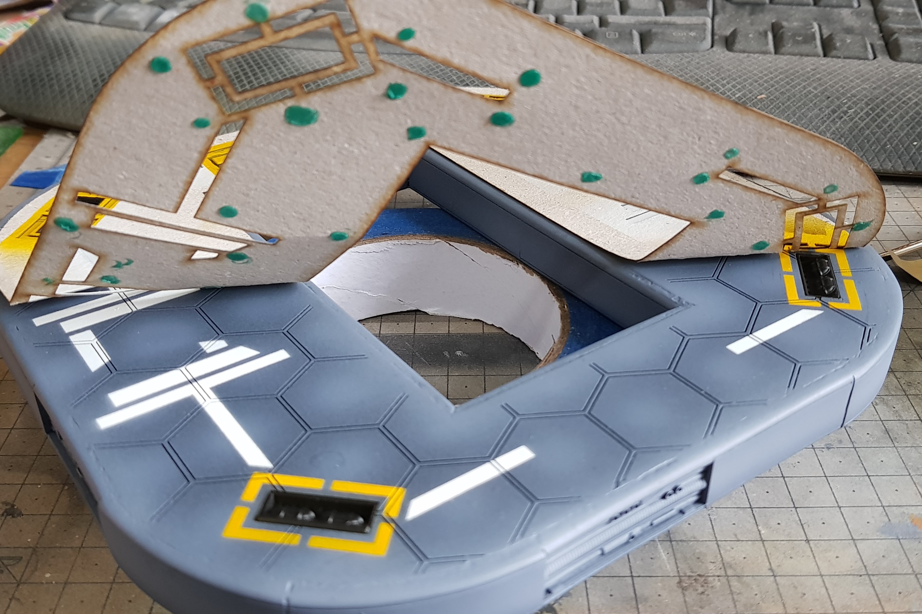
So I am not finished yet but couldn’t resist putting everything together. So happy so far. Last section needs to be designed, everything weathered, pipes put in, more painting to be done, automated truck and aircraft. Lots to do.
Closeup of the container. I will probably need to make one more of these for this model but this is just for the moment.
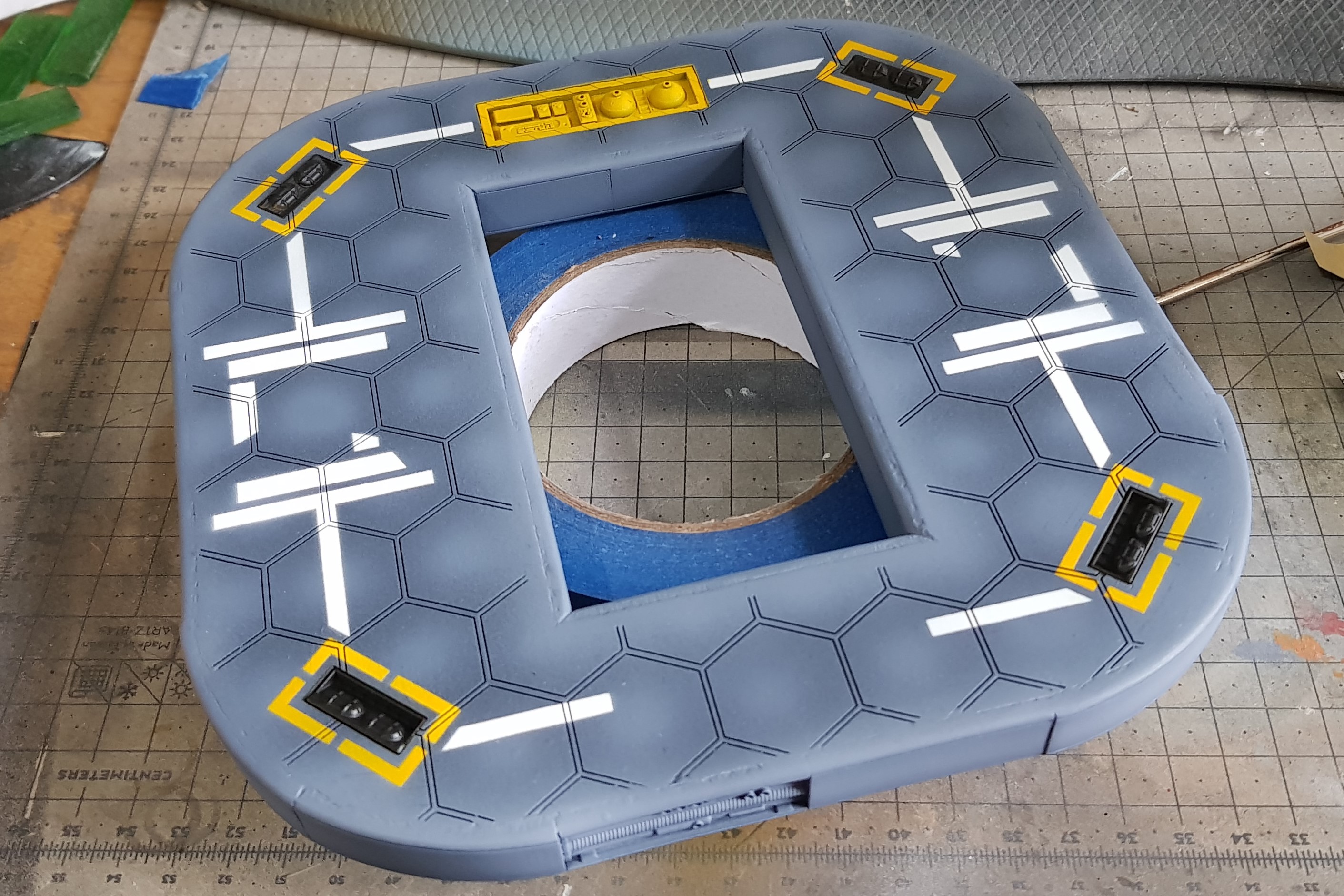
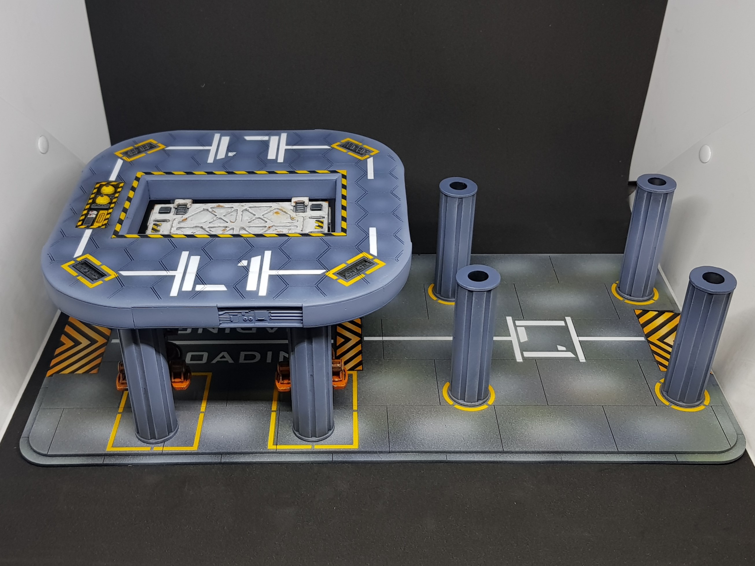 Progress so far on the landing pad. to big for photo booth.
 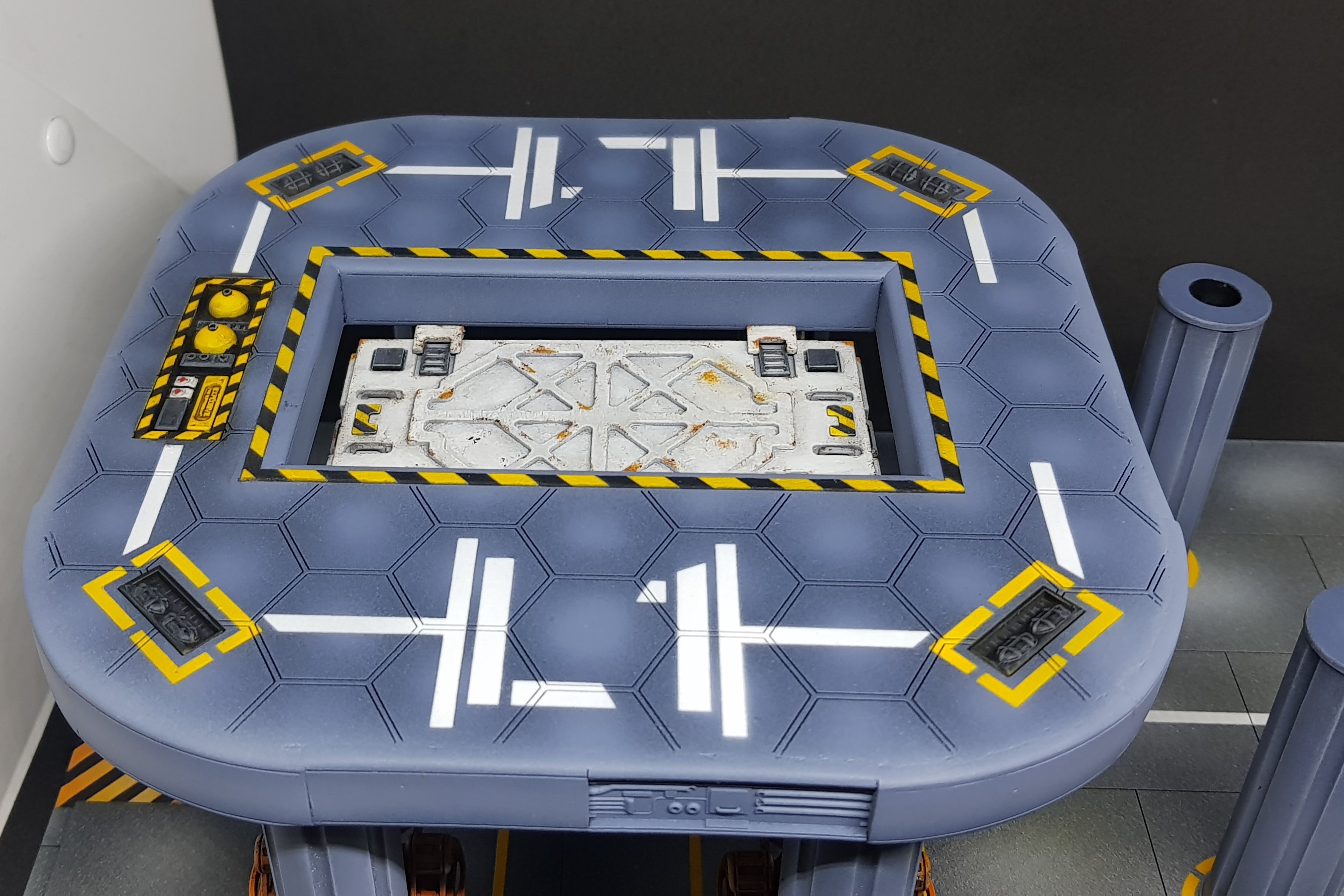 Closeup of the container. I will probably need to make one more of these for this model but this is just for the moment.
 That’s where I am at the moment. I hope to get more done this weekend but drinking is too alluring to keep going. I want to get to the design stage of the control tower next week which involves finishing the painting and adding dressing to the platform.
Much more to come.
The devils in the detail
So I didn’t manage to get this done on Sunday. It took a little longer and I am still not quite done but I am done enough to start to design the next section.
I took a look at how this was going to be assembled and I got to the stage where I had to glue the platform for the columns,
Before this was done I needed to weather this as I wouldn’t be able to easily get in. There still will be a final weathering stage but I need to get the bulk of the work done.
I also liked and disliked how much each part popped and it felt like components stuck together and not a structure.
The final result should be a well maintained and used facility, not abandoned and not entirely safe/ A few bodge jobs done to keep things running. This will be the oldest building of all as I imagine this was built to allow the delivery of building materials for the building of the industrial complex.
The first thing I done was paint the exposed panels.
I put on some thinned oil paints black, brown and orange, rubbed in with a rag and then went in with another rag and removed a lot of that was put on. This had the effect of making the stark white paint muted and giving everything a more uniform tone.
 Effect after first weathering pass.
I added some streaks using AK interactive streaking rust and streaking grime. I then went in with a brush and neatened this with some thinner. this gives a subtle rained on effect I done this to the columns and on any vertical surface.
 Side of the platform.
 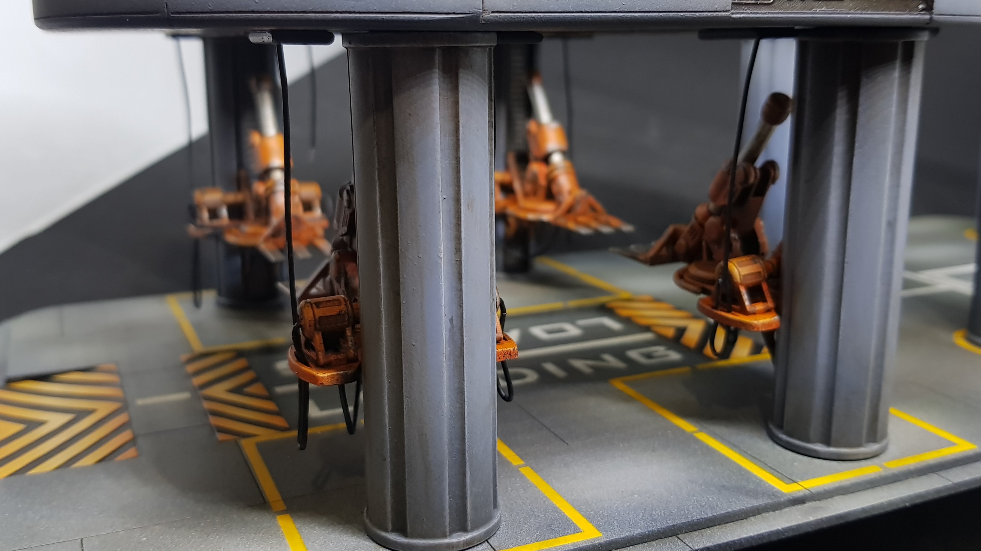 column
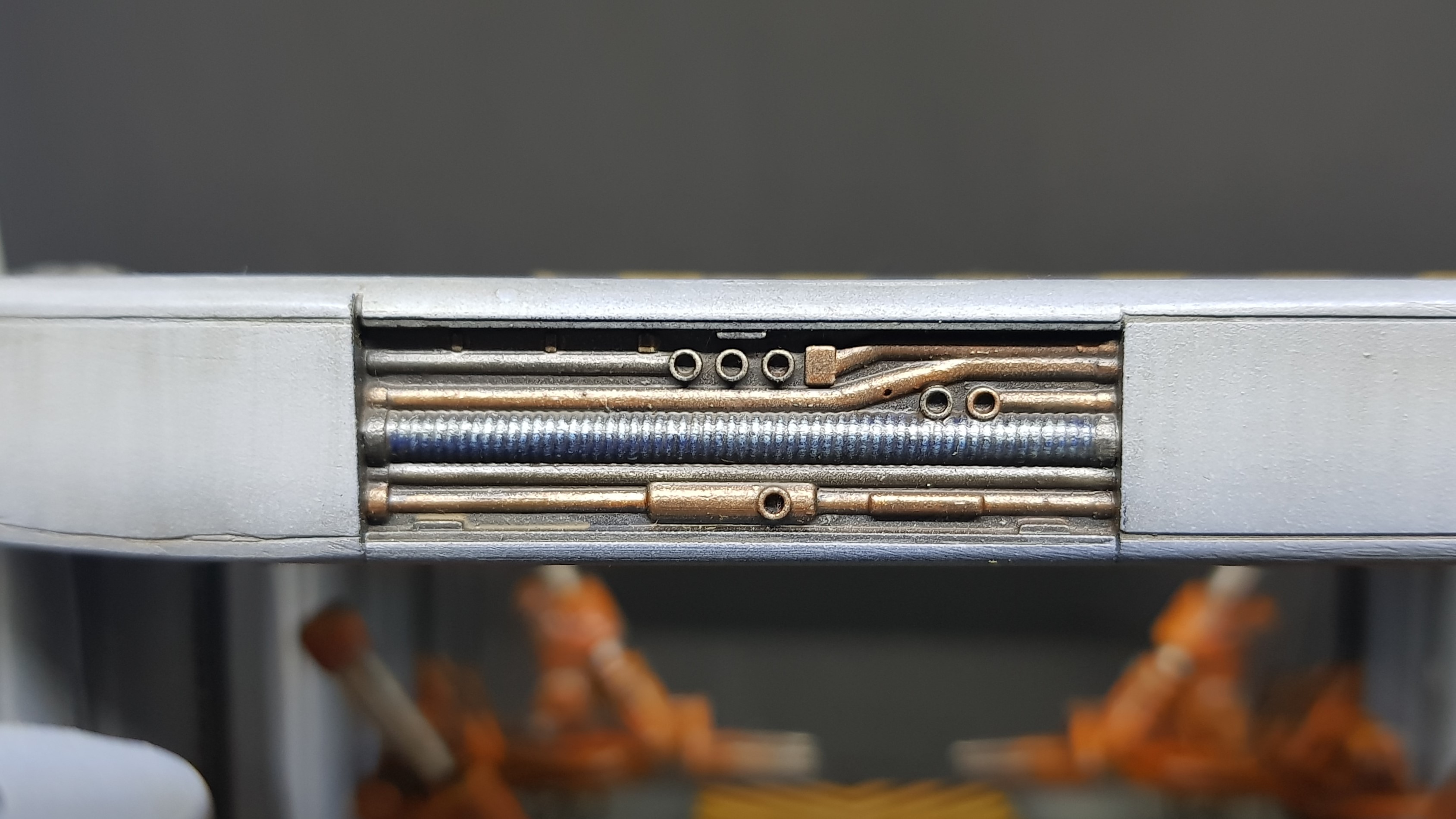
I then got the chance to start to add some cables.
First I needed to glue down the platform. This was done with superglue into the peg and holes I created earlier.
These are not “plugged in” in the same manor on each of the robots. some have been connected in serial and parts cut and swapped ports. Generally anything to make them work. I used solid core ethernet cable strands so when these don’t droop naturally as this would have been a nightmare if I used stranded wire. This may need a little touch up before I am done as it required lots of touching. Also the positions I chose should not get bashed.
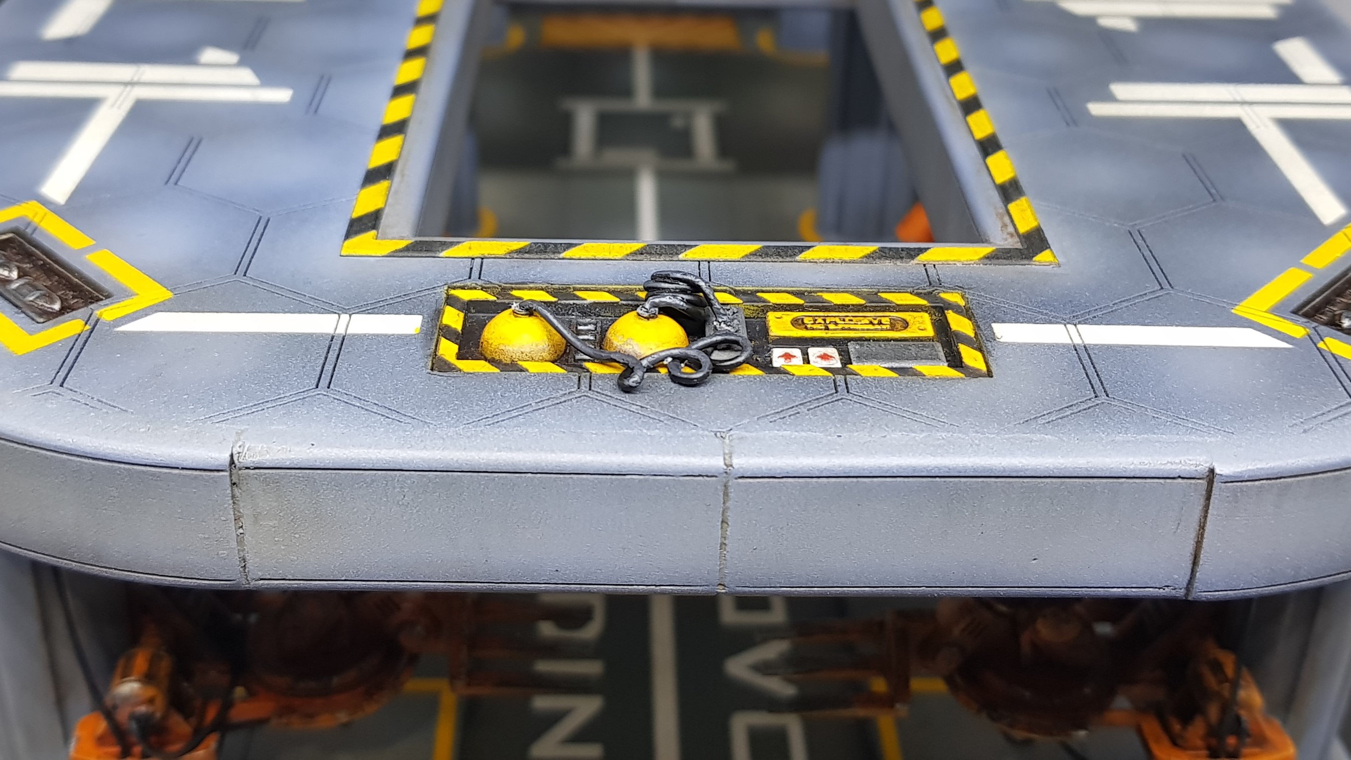 The none finished cable setup for the emergency equipment. This has to have a nozzle made and another hose added.
 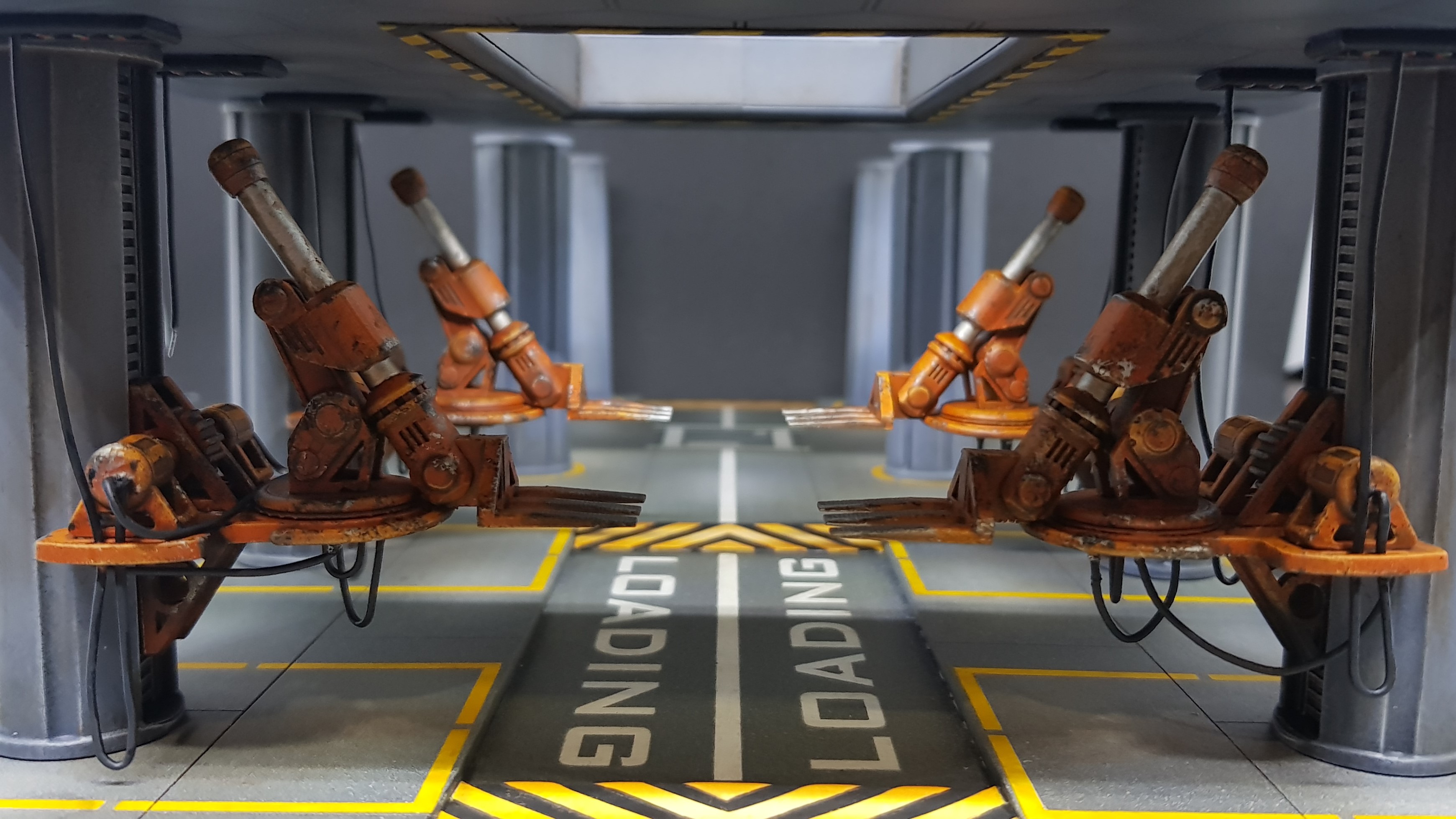 The vertical hoses were added and threaded through the robot platforms to keep them out the way during suggested movement.
 This is where I go quiet for about a week while I start to design the com tower. I have a few ideas but I have also had more ideas for more buildings which I may start on but cant start yet until I finish this.
I am still very much open to ideas. Specifically what type of doorway I should have from the building to the platform. Should this suggest a kind of draw bridge, an old repurposed airlock from a bigger dock or something else?
More to come.
The next stage & math... Lots of math
Over the weekend I started to draw, designing the com tower that would fit onto the 4 pre done pillars. I am at the stage where I am going to stop drawing and start making again. I am home sick at the moment but my head is clear enough to finish the drawings that I need.
The design has taken a number of twists along the way.
I had to think about the roots of this project and what I wanted to achieve. Not only the end result I wanted to experiment with better ways to use the tools I have and develop or discover techniques. I have used a lot of old tricks but everything 3D printed here is pretty new to me and merging laser cut MDF and card into the mix is also a new combination to me. I still have not pushed the limits of the laser cutter or the 3D printer.
Time to start pushing those boundaries.
I started with the staircase. I looked at industrial staircases and existing 28mm ones . These were rather basic but easily achievable. Not exactly pushing the design or boundaries. I wanted to break up symmetry of the second section as the first is very symmetrical, this should add visual interest in the object but in doing so I had some more room to play with.
I decided to scrap the boxy staircase and put something I have not seen done in 28mm before. A modern / industrial spiral staircase. I have been told by lots of people 15 – 20 years ago that this was one of the most complex objects to make and for it to be correct at any scale (including 1:1)… what do they know.
I started drawing and yes it makes your head hurt. Even with modern software to design in 3D, Making the shapes and have it work so you don’t have to crawl up the stairs is a challenge.
I ended up with a 28 degree section for the tread. Each raiser should be 3 point something mm high, I rounded down to 3 to make my head hurt less. To draw you need to make all the steps and move them 28 degrees around the axis which in my case is a part of an old GW paintbrush. I ended up with 31 steps at 2mm each and 30 1mm spacers.
Even reading the above hurt my head. So I had my staircase. Great… or not. Still too simple. So I decided to make a tread for each step but I wanted to keep the industrial look. Great easy just laser cut some plastic mesh… not so fast. The type of plastic the mesh I was thinking of, will laser cut but it will also likely produce toxic fumes. No thanks. I have ordered some fibreglass mesh which should be much thinner and not produce fumes I cant deal with (still not going to huff it).
Still not enough. what if my little people fall over and die before they get to the top. People will most likely be ARO’ing anyone who runs up the stairs. So I needed a safety rail of course. So I put balusters on each of the steps these will be paperclips.
That left me with a sore head. I still don’t know how I am going to print the handrail but even drawing it wasn’t pleasant but I did find an easy way after about an hour which was draw 3D curves connecting each of the balusters making the sketch into a pipe and then cutting out the holes that the balusters could fit into.
I then extended and cut the hole in the base to provide a lining.
To the left I will be placing a movable looking bridge over to the landing pad. and the basic shape of the building was set I wanted the edges curved and will be doing this on the laser cutter. but will finish the design later. There will be two ladders going from the first to the second floor.
That left the right section. I was still worries about my models safety. I will be placing boxes etc up there to provide actual cover for models but what if that stuff was not there. I know I needed another handrail. Thankfully this one was much faster.
Congratulations if you just read the ramblings above I am aware that this is quite long here is far too few pictures to balance the text.
 The entire drawing as it stands. new colours added to represent actual materials used.
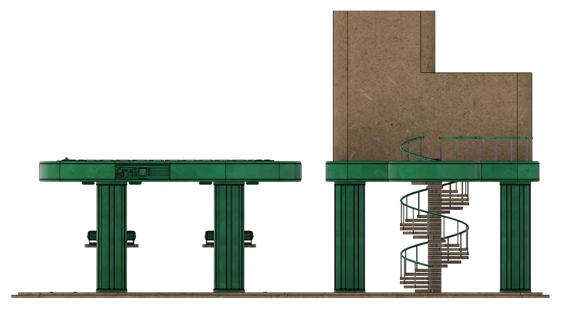 Side view showing the helix that is the stairs.
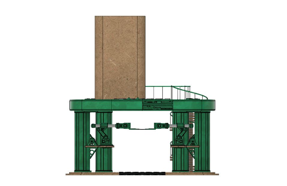 Front view showing the break in symmetry.
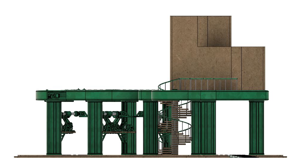 corner view showing the intrest point when not viewed from the front. I hope this draws the viewer in.
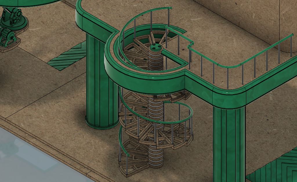 Zoomed in on the staircase
So that’s the design so far. I hope to get some time this weekend to start to build this. I don’t think I will finish it to the same level as the other parts until the building is done. I am going to build it though.
I see lots of swearing in my future.
More to come.